
Motion estimation device, motion estimation method, motion estimation integrated circuit, and picture coding device

A technology for motion detection and image formation, applied in image communication, television, electrical components, etc., can solve problems such as huge number of processing cycles, difficult address calculation, increased circuit area, etc., and achieve the effect of reducing the number of data transmissions

Inactive Publication Date: 2011-06-22
SOCIONEXT INC
View PDF1 Cites 0 Cited by
  • Summary
  • Abstract
  • Description
  • Claims
  • Application Information

AI Technical Summary

Problems solved by technology

[0046] So, in progress Figure 7 In the case of pixel transfer near the circle mark in (c), the address does not match in the part that straddles the area HLA, and data access cannot be performed with a general raster address.
Also, since the horizontal position across the 0 address depends on the vertical position, it cannot be uniquely determined, and address calculation is more difficult.
[0047] As described above, in the local memory 811 for reference, when it is necessary to perform FIFO management on the physical address of the area composed of a combination of rectangular areas, the address is reused at the unfilled pixel space position, so it is very easy Difficult to handle, requiring not only multiplication operations, but also a lot of division operations and remainder calculations
Therefore, the result of requiring complex address calculations has the following problems: in the case of hardware installation, the circuit area increases, or the operation timing around the processing frequency is strict, and on the other hand, in the case of software installation, a huge amount of time is required. Processing cycles

Method used


Image

  • Motion estimation device, motion estimation method, motion estimation integrated circuit, and picture coding device
  • Motion estimation device, motion estimation method, motion estimation integrated circuit, and picture coding device
  • Motion estimation device, motion estimation method, motion estimation integrated circuit, and picture coding device

Examples


no. 1 Embodiment approach

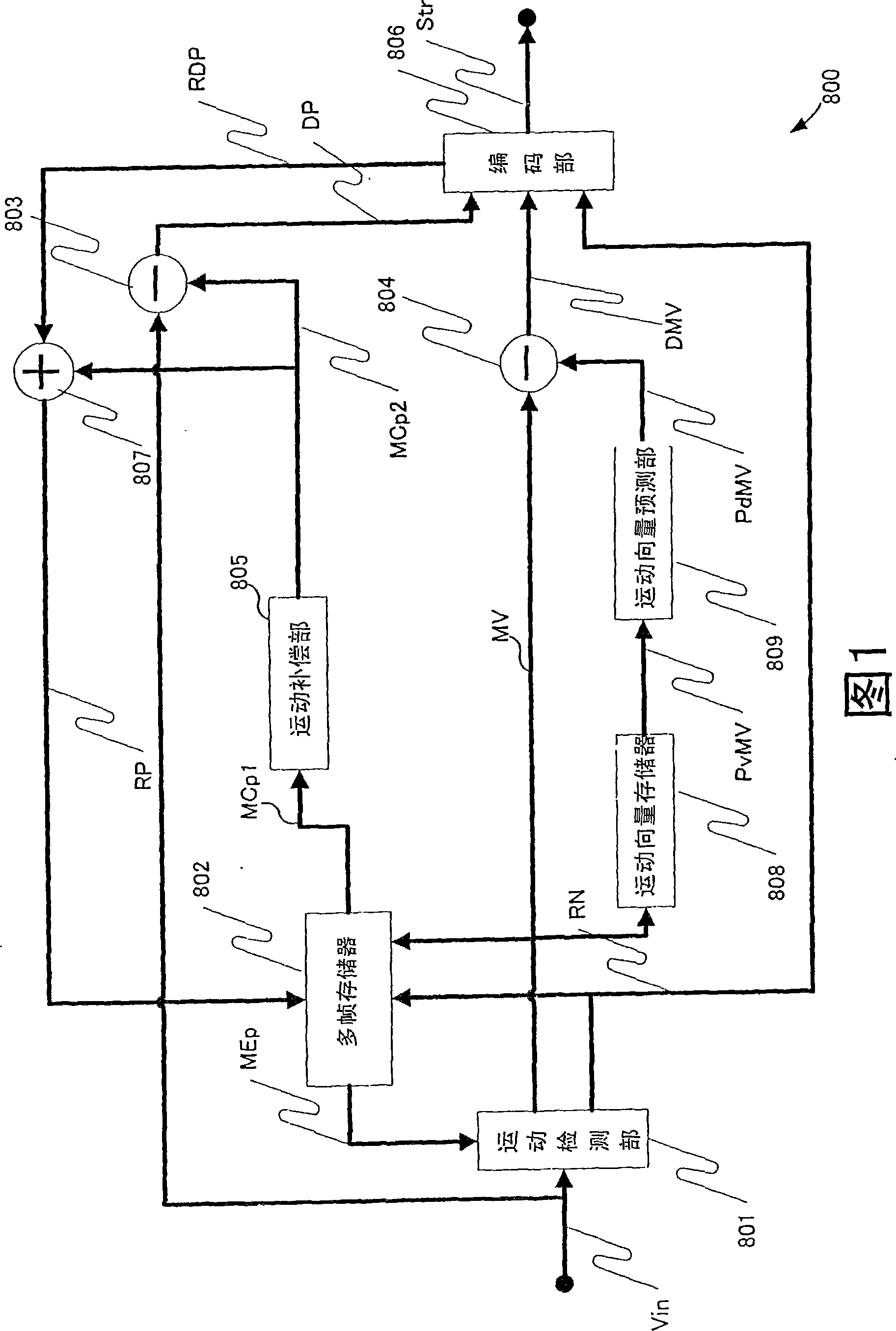
[0095] Figure 8 It is a block diagram showing the configuration of an inter-picture predictive encoding device using the motion detection device according to the first embodiment of the present invention. Additionally, for illustrations with figure 1 In the block diagram of the conventional inter picture predictive coding apparatus shown, the same parts are assigned the same symbols, and their descriptions are omitted.

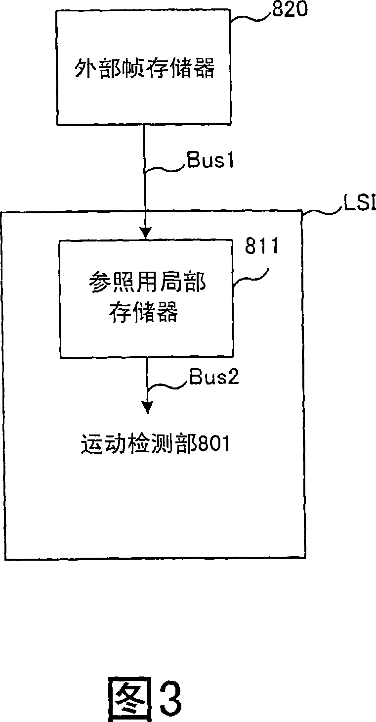
[0096] The inter-picture predictive encoding device and the figure 1 The differences of the conventional inter-picture predictive coding apparatus shown are that an external multi-frame memory 820 and an internal reference memory 820 are provided instead of the multi-frame memory 802 , and a reference memory management unit 812 is added. The internal reference memory 830 is provided inside the LSI including constituent elements other than the external multi-frame memory 820 in the inter-picture predictive encoding device. The external multi-frame memory 82...

no. 2 Embodiment approach

[0132] The operation of the internal reference memory 830 controlled by the reference memory management unit 812 in the second embodiment will be described below.

[0133] Figure 15 It is a schematic diagram showing a management area for storing reference image pixels used in the motion detection device according to the second embodiment of the present invention. In the second embodiment of the present invention, in the logical space on the cache 106, the image width is divided into powers of 2 in the horizontal direction, and the vertical height is set to the height L of the next acquisition area ARenew. Segment, the above-mentioned segments are cyclically managed by FIFO. In this figure, extents 1 to 9 are shown cyclically appearing in the logical space. The physical map memmap2 represents the state of the configuration section 1 to section 9, and in the area of ​​section 9, the area indicated by dense dots is written in the area indicated by sparse dots.

[0134] Furthe...

no. 3 Embodiment approach

[0149] The operation of the internal reference memory 830 controlled by the reference memory management unit 812 in the third embodiment will be described below.

[0150] Figure 18 It is a schematic diagram showing a management area for storing reference image pixels used in the motion detection device according to the third embodiment of the present invention. In the third embodiment of the present invention, in the cache memory 106, the virtual logical space whose width is a power of 2 in the horizontal direction is divided into an appropriate width of a power of 2 in the horizontal direction and a height of 2 in the vertical direction. Assuming that the segment with the height L of the area ARenew is acquired next time, the above segment is cyclically managed by FIFO. Here, since the extent has a power-of-two width, an invalid area may be generated in the management area even at the right end of the reference picture RefPic. In this figure, a state in which extents 1 to ...


PUM


Abstract

Provided is a motion estimation device in which an amount of pixel data transferred from an external frame memory to an internal reference local memory is reduced. By the motion estimation device, it is possible to reduce a memory capacity and a size or processing of a circuit controlling the pixel transfer. In a reference memory control unit and an internal reference memory, a height of a area to be updated is set to L pixels, where L is power of 2, a logical address segments, whose size is suitable for address calculation, are allocated to picture space, and FIFO management is performs. In another application, an assistance memory is added, and another element other than the assistance memory performs the FIFO management for rectangular areas in an image of a conventional width. As a result, the address calculation is simplified, which makes it possible to reduce an embedded circuit for the reference memory control unit and the internal reference memory.

Description

technical field [0001] The present invention relates to a motion detection device, a motion detection method, a motion detection integrated circuit, and an image encoding device for detecting motion of blocks constituting an image. Background technique [0002] In recent years, the multimedia era of comprehensive processing of sound, image and other pixel values ​​has ushered in, and the means of transmitting information from the past information media, such as newspapers, magazines, TV, radio broadcasts, telephones, etc., to people has been proposed as multimedia Object. Generally, the so-called "multimedia" not only displays text, but also associates graphics, sounds, and especially images. However, if the above-mentioned past information media is to be used as a multimedia object, it is necessary to express its information in digital form. [0003] However, if the amount of information that the above-mentioned various information media have is estimated by the amount of ...

Claims


Application Information

Patent Timeline
Patent Type & Authority Patents(China)
IPC IPC(8): H04N7/26H04N7/32H04N19/50H04N19/423H04N19/426H04N19/503H04N19/51
CPCH04N19/00781H04N19/0063H04N19/00587H04N19/0049H04N19/00733H04N19/00515H04N19/51H04N19/61H04N19/426H04N19/433H04N19/523
Inventor 井口雅保重里达郎田中健
Owner SOCIONEXT INC
Learn More