
Image sensing apparatus, image sensing system, and image sensing method

A camera device and pixel technology, which can be used in TV system scanning details, TV system components, image communication, etc., and can solve problems such as inability to obtain high-quality images, insufficient exposure, and image S/N deterioration

Inactive Publication Date: 2007-10-03
SEIKO EPSON CORP
View PDF1 Cites 28 Cited by
  • Summary
  • Abstract
  • Description
  • Claims
  • Application Information

AI Technical Summary

Problems solved by technology

However, in the case of realizing it with a single camera, as described above, when performing high-speed photography for stable control, the S / N of the image deteriorates due to insufficient exposure, and images of quality for other purposes cannot be obtained.

Method used


Image

  • Image sensing apparatus, image sensing system, and image sensing method
  • Image sensing apparatus, image sensing system, and image sensing method
  • Image sensing apparatus, image sensing system, and image sensing method

Examples


Embodiment Construction

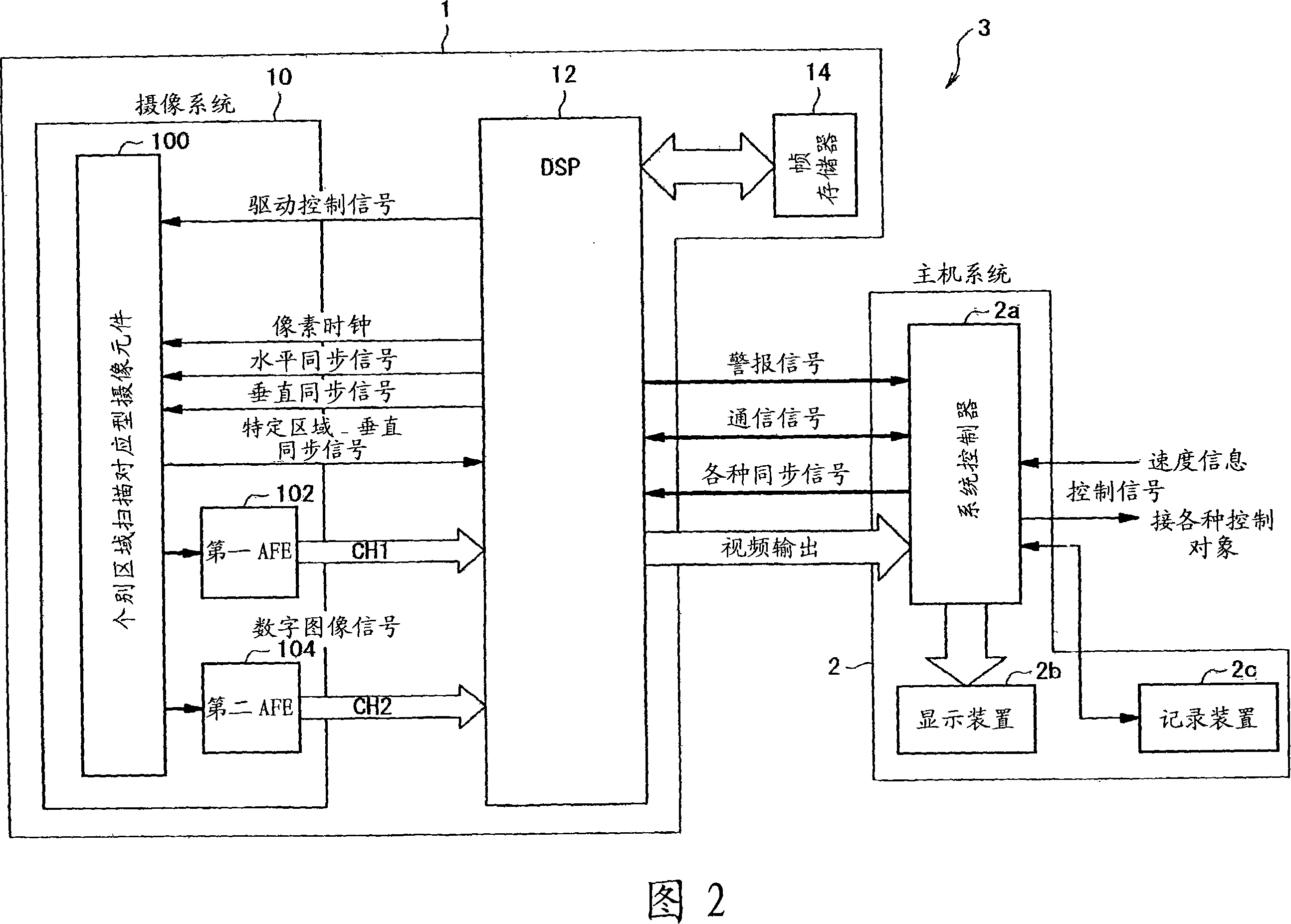
[0113] Hereinafter, embodiments of the imaging device of the present invention will be described with reference to the drawings. 1 to 13 are diagrams showing an embodiment of the imaging device 1 of the present invention.

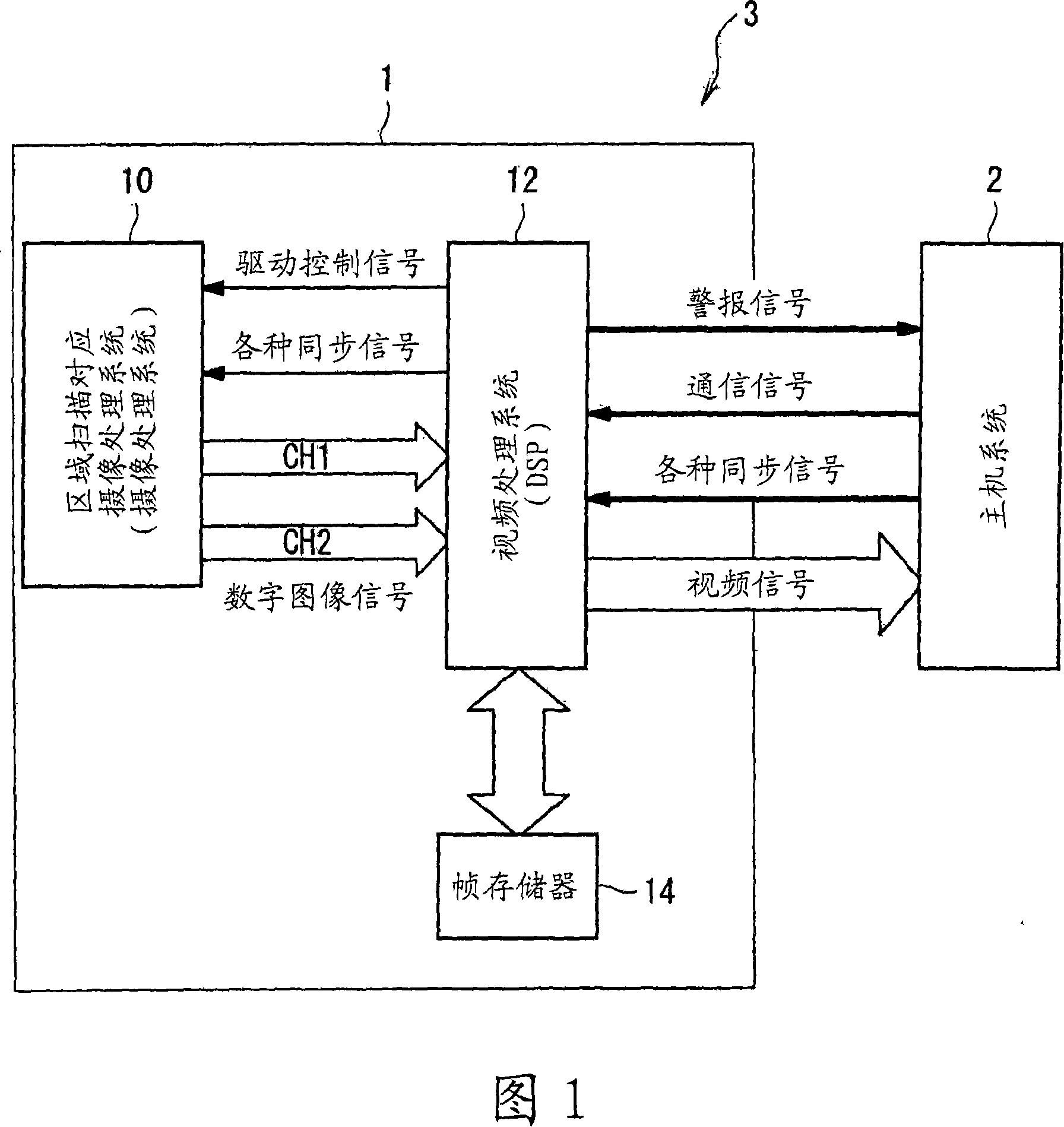
[0114] Next, based on FIG. 1, the schematic configuration of the imaging system 3 to which the imaging device 1 of the present invention is applied will be described. Here, FIG. 1 is a block diagram showing the schematic configuration of the imaging system 3 of the present invention. In addition, an object of the imaging system 3 of the present invention is to mount the imaging device 1 on a moving body and monitor the subject of interest (target object) in front of the moving body.

[0115] As shown in FIG. 1, the imaging system 3 is configured to include an imaging device 1, which takes a normal exposure time (a time arbitrarily set by the user or the like) to the sensor unit array 56 during one frame period (one exposure period). An image obtained by exposin...


PUM


Abstract

To provide an image sensing apparatus capable of simultaneously capturing both a high frame rate image from which a target object can be detected at high speed and its shape can be extracted, and a normal image of high image quality that a human or a machine can recognize, and generating control data for high-speed control based on the high frame rate image. An image sensing system 3 is configured to include an image sensing apparatus 1 and a host system 2. The image sensing apparatus 1 senses an image using the exposure of a normal exposure time to an overall exposure area of a sensor cell array 56 within one normal exposure period, senses an image using the exposure of a plurality of kinds of exposure times to a specific area (constituted of a part of the exposure area) of the sensor cell array 56 within the same one frame period, and generates data for control based on the sensed image data of the specific area. The host system 2 acquires sensed image data of the normal exposure time from the image sensing apparatus 1, records and holds the relevant sensed image data, displays the image or controls a control object based on the data for control acquired from the image sensing apparatus 1.

Description

Technical field [0001] The present invention relates to an imaging device, which can read out charges from a photoelectric conversion element using a destructive readout method and a nondestructive readout method. Background technique [0002] In recent years, surveillance cameras mounted on moving bodies have attracted much attention. For example, an in-vehicle camera for surveillance installed in a car can be cited. Examples of applications of the vehicle-mounted camera include detecting center lines or guardrails, detecting vehicle distances, and detecting sudden changes in contrast at tunnel entrances and exits. These recognition results and detection results, for example, are output to a control unit of a predetermined control target (for example, brakes, steering, alarm systems, etc.), and the control unit controls the control target based on the detection results to prevent human carelessness Accidents, respond to sudden changes in the situation, etc. [0003] In addition,...

Claims


Application Information

Patent Timeline
IPC IPC(8): H04N5/225H04N5/335H04N5/232H04N3/15
Inventor 仓根治久
Owner SEIKO EPSON CORP
Learn More