
Vacuum heat-insulating material and manufacturing method thereof

A technology of vacuum heat insulation material and manufacturing method, which is applied to chemical instruments and methods, heat exchange equipment, and pipeline protection through heat insulation, etc., which can solve the problems of large cost burden, small quality, and large shape and volume, and achieve heat energy reduction and improvement. transportability effect

Inactive Publication Date: 2007-10-03
HITACHI APPLIANCES INC
View PDF1 Cites 7 Cited by
  • Summary
  • Abstract
  • Description
  • Claims
  • Application Information

AI Technical Summary

Problems solved by technology

In either case, the inorganic fiber polymer without binder has a large volume but a small mass, so the cost of recycling and handling is relatively high, resulting in a large cost burden

Method used


Image

  • Vacuum heat-insulating material and manufacturing method thereof
  • Vacuum heat-insulating material and manufacturing method thereof
  • Vacuum heat-insulating material and manufacturing method thereof

Examples


no. 1 approach

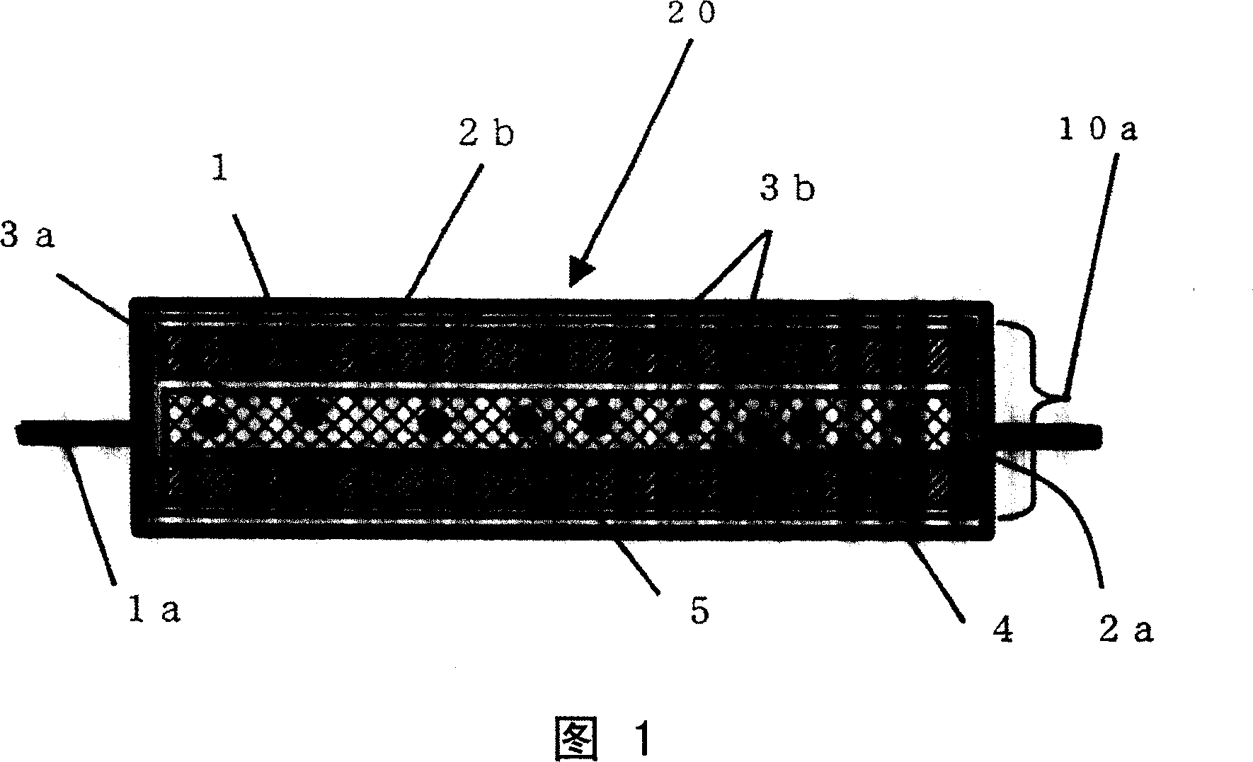
[0033] A vacuum heat insulating material according to a first embodiment of the present invention and its manufacturing method will be described with reference to FIGS. 1 to 5 . First, the structure of the vacuum heat insulating material 20 according to this embodiment will be described with reference to FIG. 1 . Fig. 1 is a cross-sectional view of a vacuum insulation material 20 according to a first embodiment of the present invention.

[0034] The vacuum heat insulating material 20 includes a core material 10a, and an airtight outer covering material 1 that stores the core material 10a, depressurizes the inside, welds the peripheral portion and seals it. The vacuum heat insulating material is constituted by a flat rectangular plate.

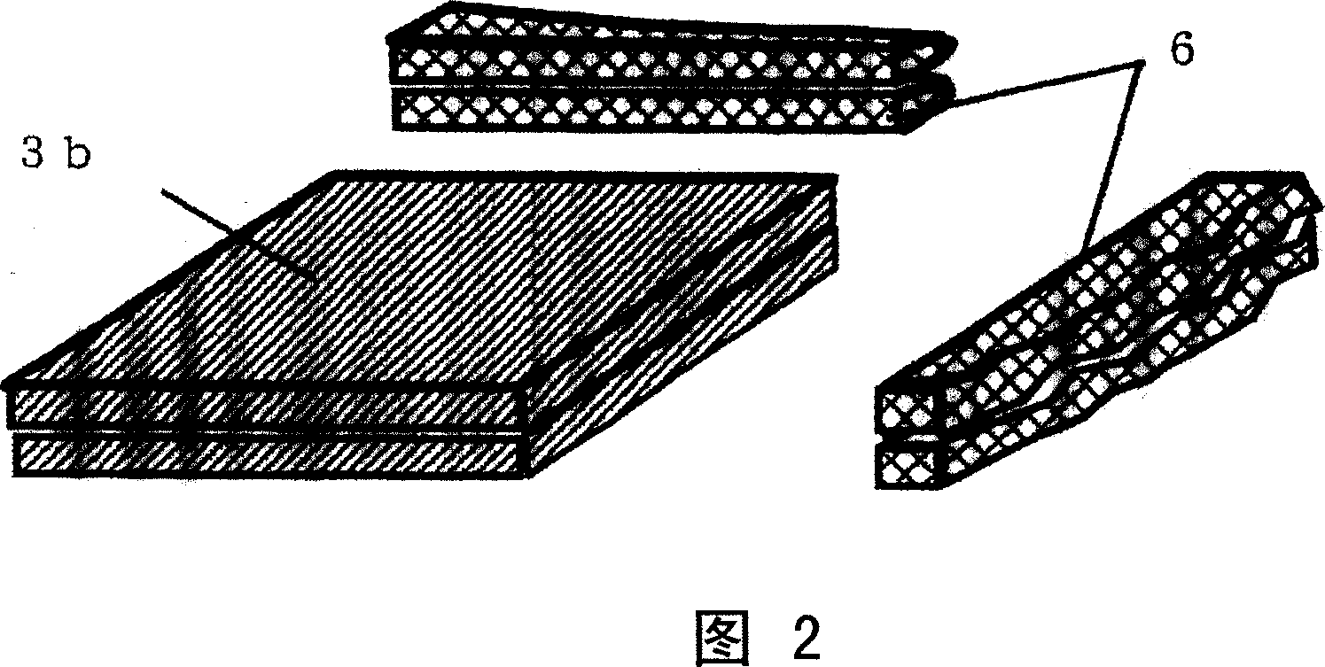
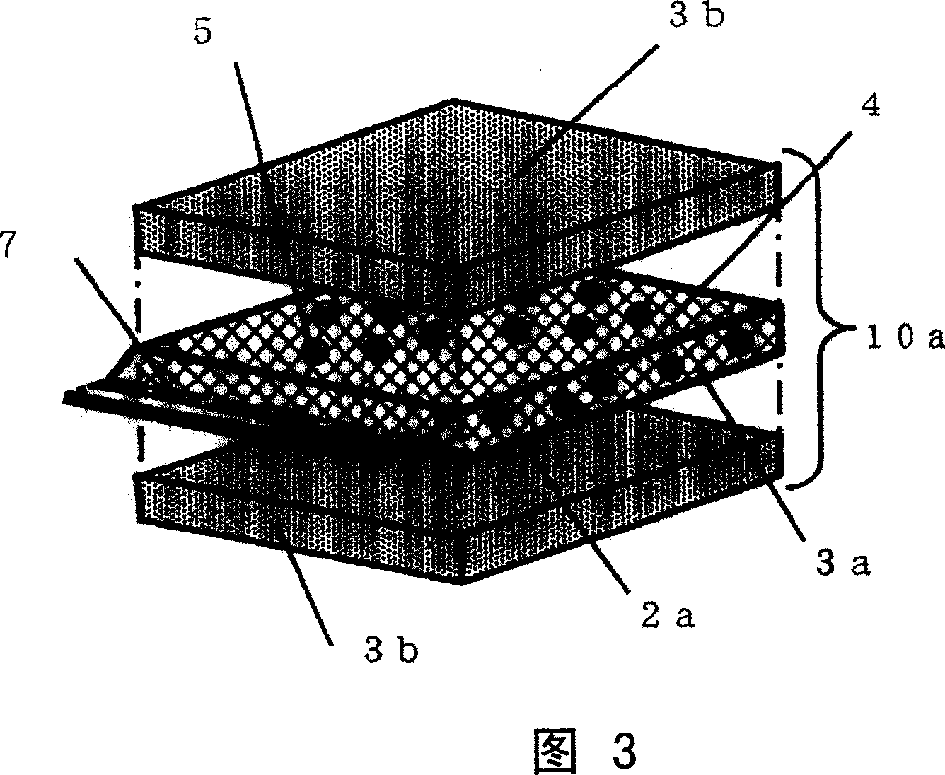
[0035] This core material 10a is a laminated body in which a plurality of heat insulators are stacked, and consists of a first core material (hereinafter referred to as "insulator a") 3a which is cut into a plurality to make the laminated body...

no. 2 approach

[0069] The heat insulator a3a is provided on at least one side to maintain the shape, and the heat insulator a3a is wrapped with the inner covering material a2a to spread the inorganic fiber aggregates of the plurality of cut sapwood products 4 so that the laminate has a desired size. The core material 10b is formed as follows: it is composed of a laminated body in which the ratio of the thermal insulator a3a relative to the whole is 50% by weight, and the thermal insulator b3b composed of an inorganic fiber aggregate not containing a binder, together with the inner covering material b2b Both sides are covered to form the core material 10b.

[0070] This second embodiment will be described using FIG. 8 . Fig. 8 is a perspective view of a core material 10b assembled in a vacuum insulation material 20 according to a second embodiment of the present invention. This second embodiment is different from the first embodiment in the points described next, and since the other points a...


PUM

PropertyMeasurementUnit
densityaaaaaaaaaa
thicknessaaaaaaaaaa
thicknessaaaaaaaaaa

Abstract

The present invention provides a vacuum heat insulation material capable of improving the transportability, reducing the electricity / heat energy and achieving the reduction of cost by recycling side section without bonding agent and manufacturing method thereof. The vacuum heat insulation material (20) stores core material (10a) composed of fiber polymer in the external housing material (1) with air impermeability, above core material is cascade body cascading a plurality of heat insulation bodies, composed of a or a plurality of heat insulation bodies cutting off the cascade body into a plurality of heat insulation bodies (ba) with desired size and arranged on a single side of the cut off heat insulation bodies and maintaining their shape, also has inner housing material (ab2b) housing the inner material (ab2b) of the core material and heat insulation body composing fiber polymer not containing bonding agent and housing the whole core material, said external housing material (1) containing said inner housing material is pressed to be vacuum state.

Description

technical field [0001] The present invention relates to a vacuum heat insulating material and a manufacturing method thereof, and is particularly applicable to a vacuum heat insulating material using sapwood and a recycling manufacturing method thereof. Background technique [0002] In recent years, from the viewpoint of energy saving, the recycling of end-of-life home appliances such as refrigerators and televisions has become an extremely important issue, and various cooperations have been made concerning the disposal of industrial waste and the recycling of its constituent materials. . In addition, from the importance of preventing global warming as a global environmental problem, energy saving is desired. For example, in relation to refrigerators, from the viewpoint of effective use of refrigeration, heat insulating materials with excellent heat insulating properties are required. The current situation is related to the development of vacuum heat insulating materials. A...

Claims


Application Information

Patent Timeline
Patent Type & Authority Applications(China)
IPC IPC(8): F16L59/02F16L59/06
CPCF16L59/065B32B5/26B32B27/12B32B27/32B32B2307/304F16L59/02
Inventor 三关隆久保田刚高桥厚美越后屋恒
Owner HITACHI APPLIANCES INC
Learn More