
Light code division multiple access decoder and manufacturing method therefor

An optical code division multiple access and codec technology, which is applied to the optical code division multiple access codec and its manufacturing field, can solve problems such as unsatisfactory product indicators, reduce product cost and size restrictions, and achieve flexible manufacturing methods. The effect of enhancing stability

Inactive Publication Date: 2007-09-26
马君显
View PDF0 Cites 6 Cited by
  • Summary
  • Abstract
  • Description
  • Claims
  • Application Information

AI Technical Summary

Problems solved by technology

[0008] In order to solve the technical problem that the optical CDMA codec based on optical fiber in the prior art has unsatisfactory product indicators due to the limitations of its own structure and manufacturing process, the present invention provides an optical CDMA coder based on a planar optical waveguide

Method used


Image

  • Light code division multiple access decoder and manufacturing method therefor
  • Light code division multiple access decoder and manufacturing method therefor
  • Light code division multiple access decoder and manufacturing method therefor

Examples


Embodiment Construction

[0021] The present invention will be described in detail below in conjunction with the accompanying drawings and embodiments.

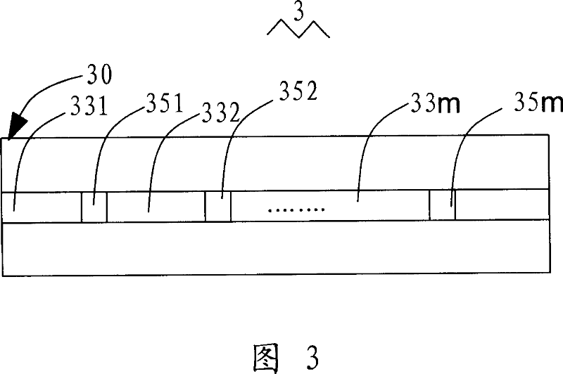
[0022] Referring to FIG. 3, FIG. 3 is a schematic structural diagram of an embodiment of an optical CDMA encoder according to the present invention. In this embodiment, the CDMA encoder 3 includes a planar optical waveguide 30, and the planar optical waveguide 30 is sequentially connected with a plurality of optical delay lines 331, 332, ..., 33m and a plurality of gratings 351, 352, ... , 35m, wherein the length of each optical delay line 331-33m is set according to the time characteristic of the codeword, and the central reflection wavelength of the grating 351-35m is set according to the wavelength characteristic of the codeword.

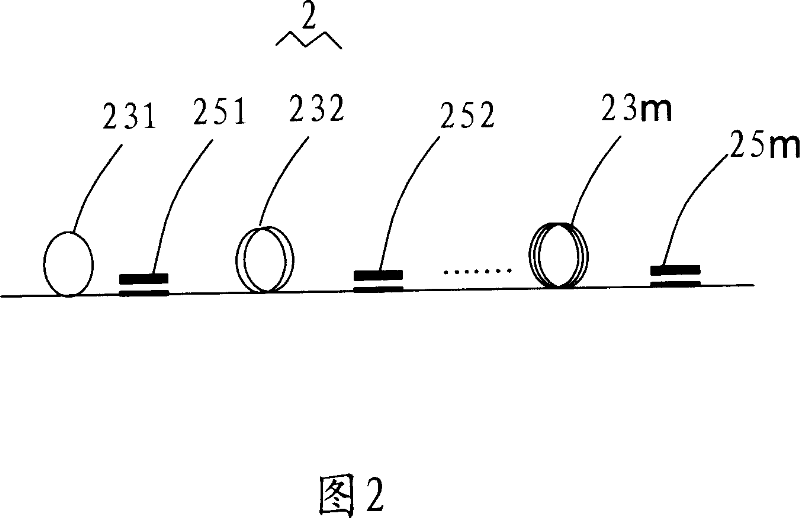
[0023] Although the overall topology of the optical CDMA codec based on the planar optical waveguide of the present invention is roughly the same as the overall topology of the optical fiber codec shown in Figure 2, the ...


PUM


Abstract

This invention relates to one light code multi-address decoding device and its process method, wherein, the decode device comprises plane light waveguide integrated with series multiple light time lag wire and multiple grating; it integrates light time lag wire and grating through plane forming decoder.

Description

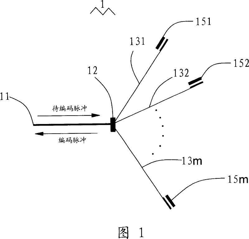
【Technical field】 [0001] The invention relates to an optical code division multiple access (Optical CDMA) codec and a manufacturing method thereof, in particular to an optical code division multiple access codec based on a planar waveguide and a manufacturing method thereof. 【Background technique】 [0002] In principle, the existing optical code division multiple access (CDMA) codecs based on time / wavelength dual degrees of freedom generally use the combination of fiber Bragg gratings and fiber delay lines to realize coding, that is, to use specific fiber Bragg gratings to select wavelength characteristics that meet the codeword. The optical signal, and then use the fiber delay line to delay the selected optical signal pulse according to the time characteristics of the code word, so as to realize the two-dimensional encoding. [0003] As shown in FIG. 1 , the basic structure of an existing time / wavelength two-dimensional optical CDMA encoder 1 is a tree structure with one no...

Claims


Application Information

Patent Timeline
Patent Type & Authority Applications(China)
IPC IPC(8): G02B6/28H04J14/00H04B10/00
Inventor 马君显
Owner 马君显
Learn More