
Method for generating testing vector

A technology of test vectors and synchronous clocks, which is applied in electronic circuit testing, automatic power control, electrical components, etc., and can solve problems such as rising chip manufacturing costs

Inactive Publication Date: 2007-09-19
WUXI ZGMICRO ELECTRONICS CO LTD
View PDF0 Cites 10 Cited by
  • Summary
  • Abstract
  • Description
  • Claims
  • Application Information

AI Technical Summary

Problems solved by technology

However, improving the robustness of test vectors requires a lot of time and effort to do fine analysis, as well as a lot of machine testing time, which increases the manufacturing cost of the chip.

Method used


Image

  • Method for generating testing vector
  • Method for generating testing vector
  • Method for generating testing vector

Examples


Embodiment Construction

[0031] In order to make the purpose, technical solution and advantages of the present invention clearer, the present invention will be further described in detail below with reference to the accompanying drawings and embodiments.

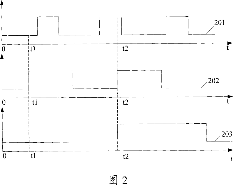
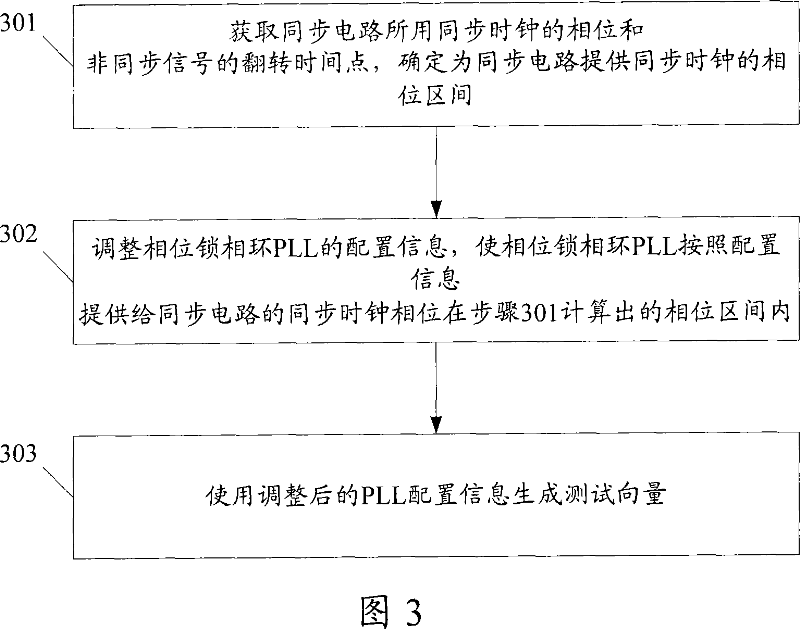
[0032] The method for generating test vectors provided by the present invention first obtains the phase of the synchronous circuit synchronous clock and the flipping time point of the asynchronous signal, and determines the phase interval of the synchronous clock for the synchronous circuit; secondly, adjusts the configuration information of the phase-locked loop PLL, so that The synchronous clock phase output by the PLL according to the configuration information is within the calculated phase interval; finally, the adjusted PLL configuration information is used to generate a test vector.

[0033] The method for generating test vectors provided by the present invention will be described in detail below.

[0034] Referring to Fig. 3, Fig. 3 is a flow...


PUM


Abstract

The present invention provides a method of generating the test vectors. The method includes: A. the phase of the synchronous clock of the synchronous circuit and the overturning time point of the asynchronous signal are obtained, and a phase interval of the synchronous clock provided for the synchronous circuit is determined; B. the configuration information of the phase locked loop PLL is adjusted to make sure that the synchronous clock phase output according to the configuration information by PLL is in the phase interval calculated in the step A; C. the test vectors are generated by using the adjusted PLL configuration information. In the present invention, test vectors can be generated through adjusting the configuration information of PLL, and in the testing process, said test vectors assure that the synchronous signals output by the synchronous circuit not generate excursion. Thus, the chips having perfect functions can all pass the test and the testing of the robustness of the vectors are improved.

Description

technical field [0001] The invention relates to a testing technology, in particular to a method for generating test vectors. Background technique [0002] With the increase of chip integration, complexity and functional requirements, in many digital circuit systems, there are functional modules in different clock domains inside the chip, and the clock signals of different phases required by these functional modules in different clock domains are determined by the internal A phase-locked loop (PLL) circuit is provided. There are also several synchronous circuits inside the chip, and each synchronous circuit samples the asynchronous signals output by the functional modules in different clock domains in the chip according to the synchronous clock in a clock domain provided by the PLL circuit to obtain a stable synchronous signal, that is, The asynchronous signals output by the functional modules of different clock domains in the chip are synchronized to one clock domain, and t...

Claims


Application Information

Patent Timeline
IPC IPC(8): G01R31/28H03L7/07
Inventor 余娜敏
Owner WUXI ZGMICRO ELECTRONICS CO LTD
Learn More