
Micro-band technical broadband power allocation/synthesizer

A kind of synthesizer, technology, applied in impedance networks, electrical components, transmission systems, etc., to solve problems such as narrow operating frequency band production

Inactive Publication Date: 2007-09-12
鞍山同方吉兆广播电视设备有限公司
View PDF0 Cites 3 Cited by
  • Summary
  • Abstract
  • Description
  • Claims
  • Application Information

AI Technical Summary

Problems solved by technology

The traditional microstrip line type RF distribution / synthesizer adopts the single-section 1 / 4 wavelength transmission line impedance transformation technology, which brings a lot of inconvenience to production due to its narrow operating frequency band

Method used


Image

  • Micro-band technical broadband power allocation/synthesizer
  • Micro-band technical broadband power allocation/synthesizer
  • Micro-band technical broadband power allocation/synthesizer

Examples


Embodiment 1

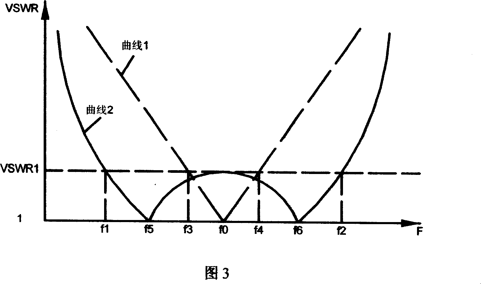
[0019] Fig. 2 is a schematic diagram of a novel broadband distribution / synthesizer. The present invention adopts the impedance conversion technology of 2 sections of 1 / 4 wavelength transmission line, and in the frequency range of 470-860MHz, the VSWR of port A is theoretically less than 1.1.

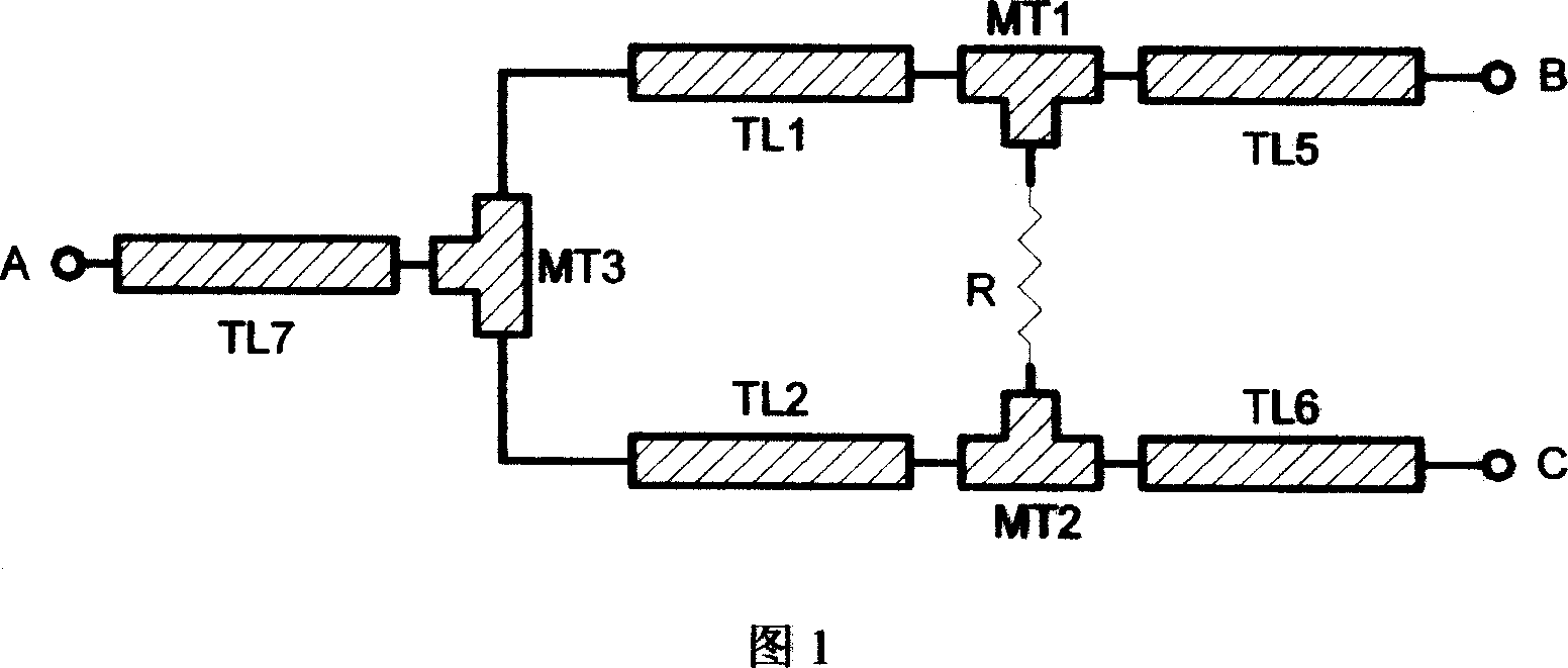
[0020] If the distribution / combiner and the power amplifier are located in the same unit box, the scheme in Figure 4 can be adopted for implementation: use a low-loss medium (in this example, polytetrafluoroethylene glass fiber board) printed circuit board to make microstrip lines TL1~TL7, MS1 It is the junction of TL1 and TL3, MS2 is the junction of TL2 and TL4, MT1 is the junction of TL3, TL5, and R, MT2 is the junction of TL4, TL6, and R, and MT3 is the junction of TL1, TL2, and TL7 of the confluence.

[0021] Let the characteristic impedances of the microstrip lines TL1, TL2, TL3, TL4, TL5, TL6, and TL7 be Z1, Z2, Z3, Z4, Z5, Z6, and Z7 respectively, and select the appropriate width ...

Embodiment 2

[0024] As shown in Figure 5, the device described in Embodiment 1 is installed in a metal box. At the same time, heat dissipation requirements need to be considered, and three coaxial 50Ω connectors (such as N-type, BNC-type etc.), the connection relationship of each part is the same as that of Embodiment 1.

Embodiment 3

[0026] 2 n (n=2, 3, 4, 5...) road distribution / synthesizer, Fig. 6 has provided 4 road distribution / synthesizer, can form 8, 16, 32... 2 roads by the same method n Road distributor / synthesizer, D1, D2, D3 in Fig. 6 is exactly the same device among Fig. 4 or Fig. 5.


PUM


Abstract

The invention relates to the wireless communication equipment technology area, specially relates to a micro belt technology wideband power distribution / synthesizer. This equipment uses two 1 / 4 wavelength impedance conversion technology, used in impedance conversion function micro fasciole TL1, TL2, TL3, TL4 length is the 1 / 4 of TL1-TL4 wave length when the working band in the center frequency signal transmited. Through choose the characteristic impedance of the impedance conversion functionmicro fasciole, causes its input / output port voltage standing wave ratio VSWR according to the Chebyshev multinomial arranged, may completely cover 470-860MHz in the UHF frequency band, reduces the part type of the serial products, facilitates the production.

Description

technical field [0001] The invention relates to the technical field of wireless communication equipment, in particular to a broadband power distribution / synthesizer of microstrip technology. Background technique [0002] RF distribution / synthesis technology is one of the key technologies in all solid-state broadcast TV transmitting equipment. The microstrip line distribution / synthesis network is a passive and reversible network, so it can be used as both a distributor and a synthesizer. With the development of technology, the RF part (including distributor, power amplifier, combiner, directional coupler, etc.) in TV transmitting equipment hopes to use broadband circuits, which can facilitate production. The traditional microstrip line RF distribution / synthesizer adopts the single-section 1 / 4 wavelength transmission line impedance conversion technology, which brings a lot of inconvenience to production because of its narrow operating frequency b...

Claims


Application Information

Patent Timeline
Patent Type & Authority Applications(China)
IPC IPC(8): H04B1/04H04B1/40H03H7/48
Inventor 丛金涛吕卫么国静董振刚
Owner 鞍山同方吉兆广播电视设备有限公司
Learn More