Non-hyperthermia heat pipe structure

A tube structure and warming technology, applied in indirect heat exchangers, heat exchange equipment, heat exchanger shells, etc., can solve the problems of heat transfer failure of heat pipes, increased manufacturing costs, waste of tube shells, etc., to achieve injection and vacuuming The process is simple, the process and manufacturing costs are reduced, and the effective length of use is improved

Inactive Publication Date: 2010-08-25
胡凯
View PDF0 Cites 0 Cited by
  • Summary
  • Abstract
  • Description
  • Claims
  • Application Information

AI Technical Summary

Problems solved by technology

[0003] The disadvantage of the above-mentioned structure of the heat pipe in the prior art is that the sealing process at both ends of the shell is complicated, and a little careless operation will cause the heat pipe to leak and cause the heat conduction heat of the heat pipe to fail
The deformation of the tube shell is seriously wasteful. The deformation not only affects the appearance, but also causes inconvenience in the direction of use of the heat pipe or the assembly space, which limits the product configuration. At the same time, the injection of the working medium of the heat pipe and the vacuuming of the tube shell can only be done once. When the vacuum pumping in the shell fails, due to the reduction of the effective length of the shell, a lot of waste of the shell is caused, which increases the manufacturing cost
It also brings a lot of inconvenience for the maintenance and reuse of heat pipes.

Method used


Image

  • Non-hyperthermia heat pipe structure
  • Non-hyperthermia heat pipe structure
  • Non-hyperthermia heat pipe structure

Examples


Embodiment Construction

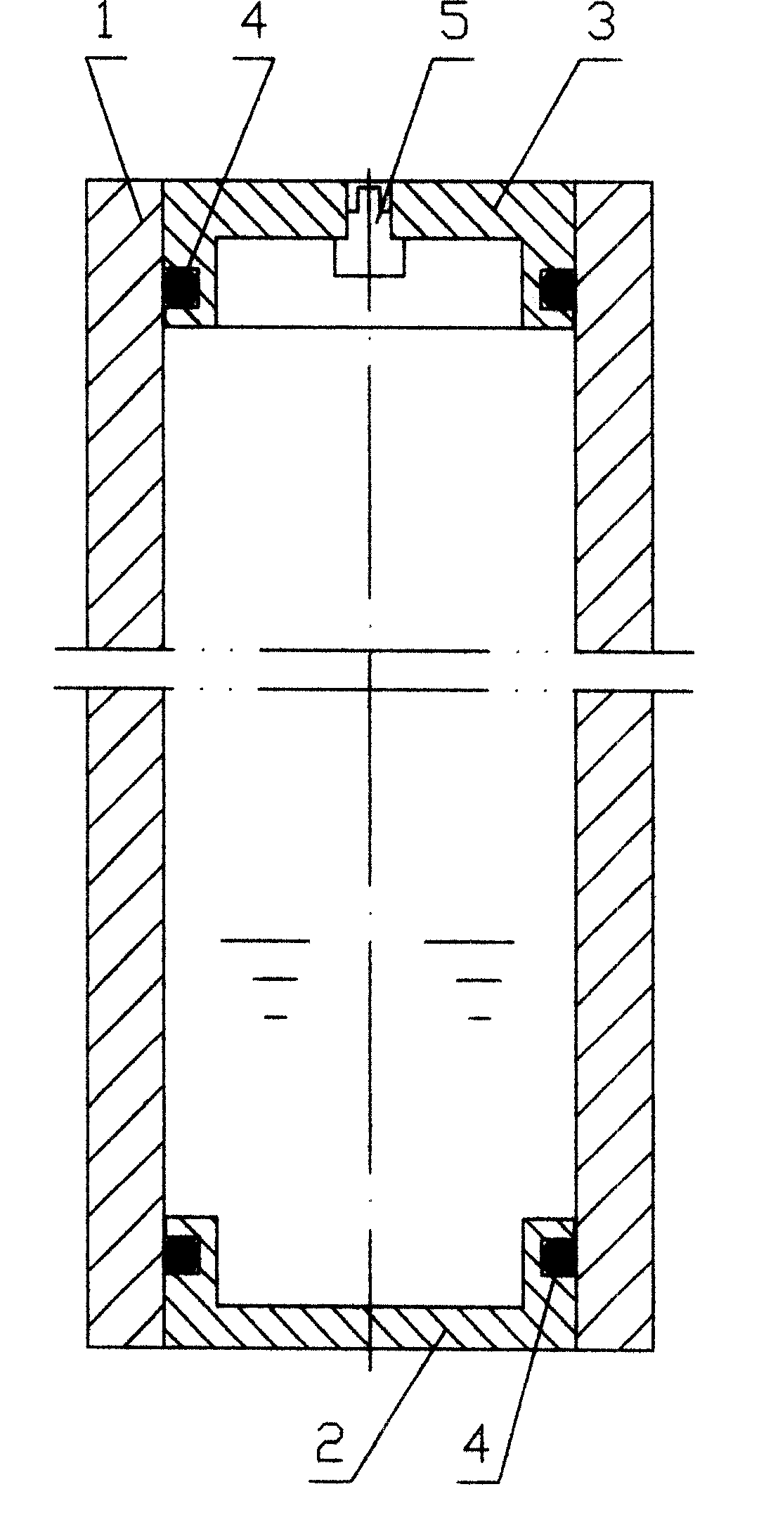
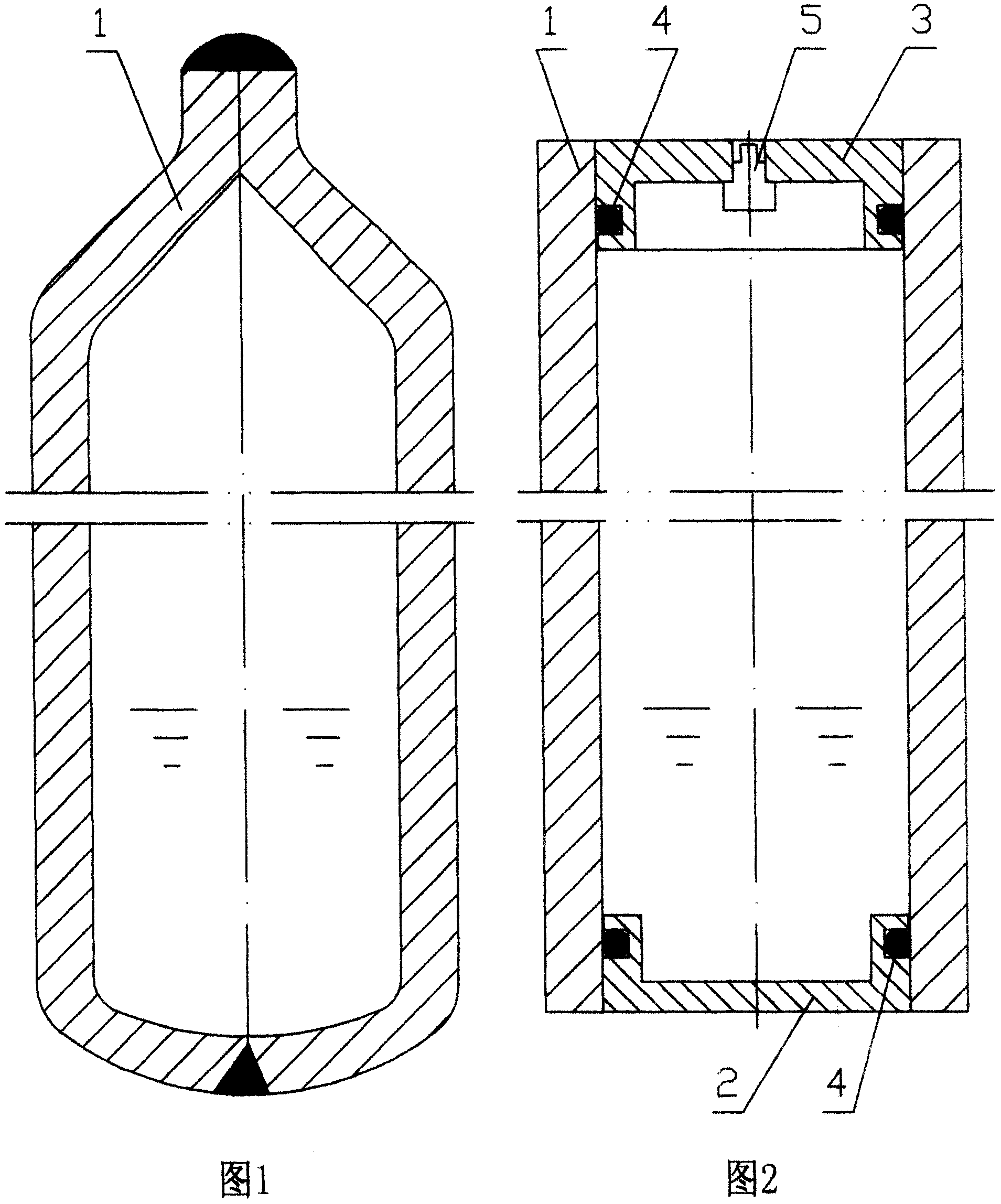
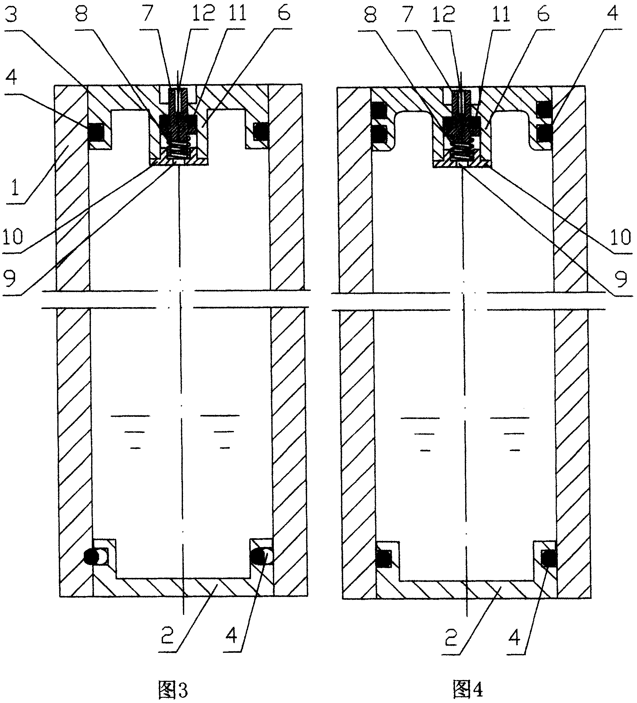
[0014] Referring to accompanying drawing 2, the non-high-temperature heat pipe structure of the present invention adopts a blind plug 2 arranged at one end of the tube shell 1, and a plugging with a one-way controllable conduction valve 5 with a central band for injecting working medium and vacuuming at the other end. 3. The mating surfaces of the blind plug 2 and the plug 3 and the shell 1 are in interference fit contact, and a sealing ring 4 is arranged between the mating surfaces of the blind plug 2 and the plug 3 and the shell 1 .

[0015] The present invention overcomes the traditional design concept of the industry, and realizes the fixing and sealing of the blind plug 2 and the plug 3 and the inner wall of the tube shell 1 by the interference fit contact between the blind plug 2 and the plug 3 and the inner wall of the tube shell 1. A large number of experiments have proved that the use of this structure can fully meet the use requirements of normal temperature heat pipe...


PUM


Abstract

It's a kind of hot tube structure of normal heat temperature which mainly solves the structure problem that seals on both sides of tube shell of heat tube, adds working medium into heat tube and The technological scheme adopted is that fixed blind plug is placed on the side of tube shell, central injection working medium and the plug of unidirectional controllable guide pass valve using to vacuumize are placed on the other side. Blind plug, plug and joint surface is interference fit, and the sealing ring is installed among them. The advantages of the invention is that sealing structure is simple on both sides of the tube shell, manufacturing technology is reduced greatly, the existing technology of manual sealing technology on both sides of the tube shell changes into continual mechanization technology like flowing water so that improving the production efficiency greatly, reducing the technology and manufacturing cost, increasing the effect length used, making the technology of injecting working medium into heat tube and vacuumizing extremely simple, and convenient to manufacture and maintain hot tubes.

Description

Technical field [0001] The invention relates to a non-high-temperature heat pipe structure, in particular to a non-high-temperature heat pipe whose two ends are sealed with a mechanical structure, and one end of the non-high-temperature heat pipe is provided with a one-way controllable conduction valve for injecting working medium and vacuuming. Non-high temperature heat pipe structure. Background technique [0002] The heat pipe is a kind of high thermal conductivity material after injecting the working medium into the shell, the shell is vacuumed, and is used for the heat dissipation of heat conduction. The existing heat pipes can be divided into high temperature heat pipes, normal temperature heat pipes and low temperature heat pipes, normal temperature heat pipes and low temperature heat pipes. Heat pipes are called non-high-temperature heat pipes, which are often used in computer CPU cooling elements and air conditioners. Their good thermal conductivity can effectively ...

Claims


Application Information

Patent Timeline
Patent Type & Authority Patents(China)
IPC IPC(8): F28F11/00F28F9/26F28D15/02
Inventor 胡凯
Owner 胡凯
Why Eureka
Try Eureka