
Method and apparatus for pump protection without the use of traditional sensors

A technology of pump speed and controller, applied in the field of pump system, can solve the problem of useless calibration power and so on

Active Publication Date: 2007-09-12
ITT MFG ENTERPRISES LLC
View PDF14 Cites 13 Cited by
  • Summary
  • Abstract
  • Description
  • Claims
  • Application Information

AI Technical Summary

Problems solved by technology

But it is not used to calibrate the power

Method used


Image

  • Method and apparatus for pump protection without the use of traditional sensors
  • Method and apparatus for pump protection without the use of traditional sensors
  • Method and apparatus for pump protection without the use of traditional sensors

Examples


Embodiment Construction

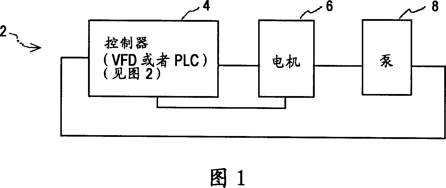
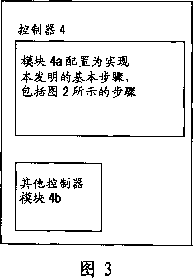
[0035] FIG. 1 shows a basic pump system, generally designated 2 , with a controller 4 , a motor 6 and a pump 8 according to the invention. In operation, the controller 4 according to the invention, by means of a field calibrated speed versus power curve for valve closure, a motor signal of speed and power (or torque) and e.g. the nominal pump speed stored in the evaluation device Calculated flow values ​​are determined based on basic published pump performance data at optimal efficiency power, valve closed power, and optimal efficiency flow. The calculated flow input for comparison with the threshold flow value can also be obtained by various techniques at various speeds using pump cutting law data and stored in an evaluation device or module (e.g. module 4a in FIG. 3 ). The flow rate is calculated from the flow calibration curve of the pump and pump and motor signals such as speed and power (or torque) or speed and power / differential pressure. Where the installation includes...


PUM


Abstract

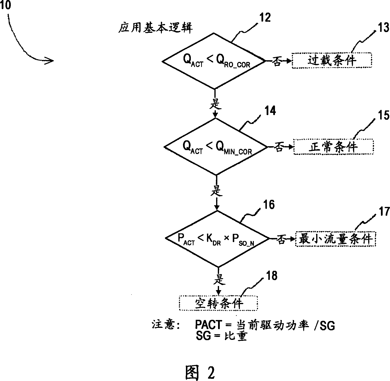
The present invention provides protection for centrifugal pumps while differentiating between dangerous operating conditions (e.g. dry running, minimum flow and runout) and / or conditions where transient conditions (e.g. closed valve operation) may occur and the protection can be revoked once the condition clears. The methodology utilizes a calculated flow value which can be mathematically determined from a calibrated closed valve power vs speed curve and / or various pump and motor parameters such as speed, torque, power and / or differential pressure or from calibrated flow curves stored in the evaluation device. The calculated flow value is then compared to threshold values of flow associated with these adverse operating conditions.

Description

[0001] Cross References to Related Applications [0002] This patent application claims priority to Provisional Patent Application no. 60 / 780,529, filed March 8, 2006, entitled "Method for Pump Protection Without the Use of Traditional Sensors" (911-2.22-1 / 05GI002), and also relates to Provisional Patent Application no. 60 / / 780,546, filed March 8, 2006, entitled "Method For Determining Pump Flow Without Traditional Sensors" (911-2.24-1 / 05GI003). The entire contents of these two provisional patent applications are incorporated herein by reference. technical field [0003] The present invention relates to a pump system having a pump including a centrifugal pump; and more particularly to a method and apparatus for pump protection without the use of conventional sensors. Background technique [0004] Other similar devices and their drawbacks are as follows: [0005] U.S. Patent No. 7,080,508 discloses a method and apparatus for torque-controlled pump protection with mechanical...

Claims


Application Information

Patent Timeline
IPC IPC(8): F04B49/00F04B49/06
CPCF04D15/0088F04D15/0066F04D15/0209F04D15/0236
Inventor 安东尼·A·斯塔瓦莱尼古拉斯·W·甘宗
Owner ITT MFG ENTERPRISES LLC
Learn More