Pulsed arc welding method

A pulse and arc welding technology, which is applied in arc welding equipment, welding medium, welding equipment, etc., can solve the problems of frequent occurrence of large-grain spatter, inability to separate molten droplets, and difficult transition, so as to reduce small-grain spatter, reduce the occurrence of large-grain spatter and Effect of smoke generation and stabilization improvement

Active Publication Date: 2007-09-12
KOBE STEEL LTD
View PDF7 Cites 39 Cited by
  • Summary
  • Abstract
  • Description
  • Claims
  • Application Information

AI Technical Summary

Problems solved by technology

Therefore, it is difficult to maintain a stable arc when performing weaving welding in a groove where the distance between the contact piece and the base metal fluctuates by about ±5 mm from the standard state.
[0013] Furthermore, in the output control device disclosed in JP-A-8-229680, it is possible to control splashing by reducing the current for a certain period of time after detecting droplet detachment. However, in the method described in this document, no matter whether the droplet is Detachment, because the pulse peak current is the same in all pulses, so if the pulse peak current is set to allow the droplet to detach, the molten metal remaining on the welding wire after the droplet detachment will be detached under the strong arc force Then, when the pulse peak value is applied, it will scatter, so that the large grains will splash frequently
In order to suppress this, if the pulse peak value is set low, there is a problem that the droplet cannot escape during the pulse peak period.
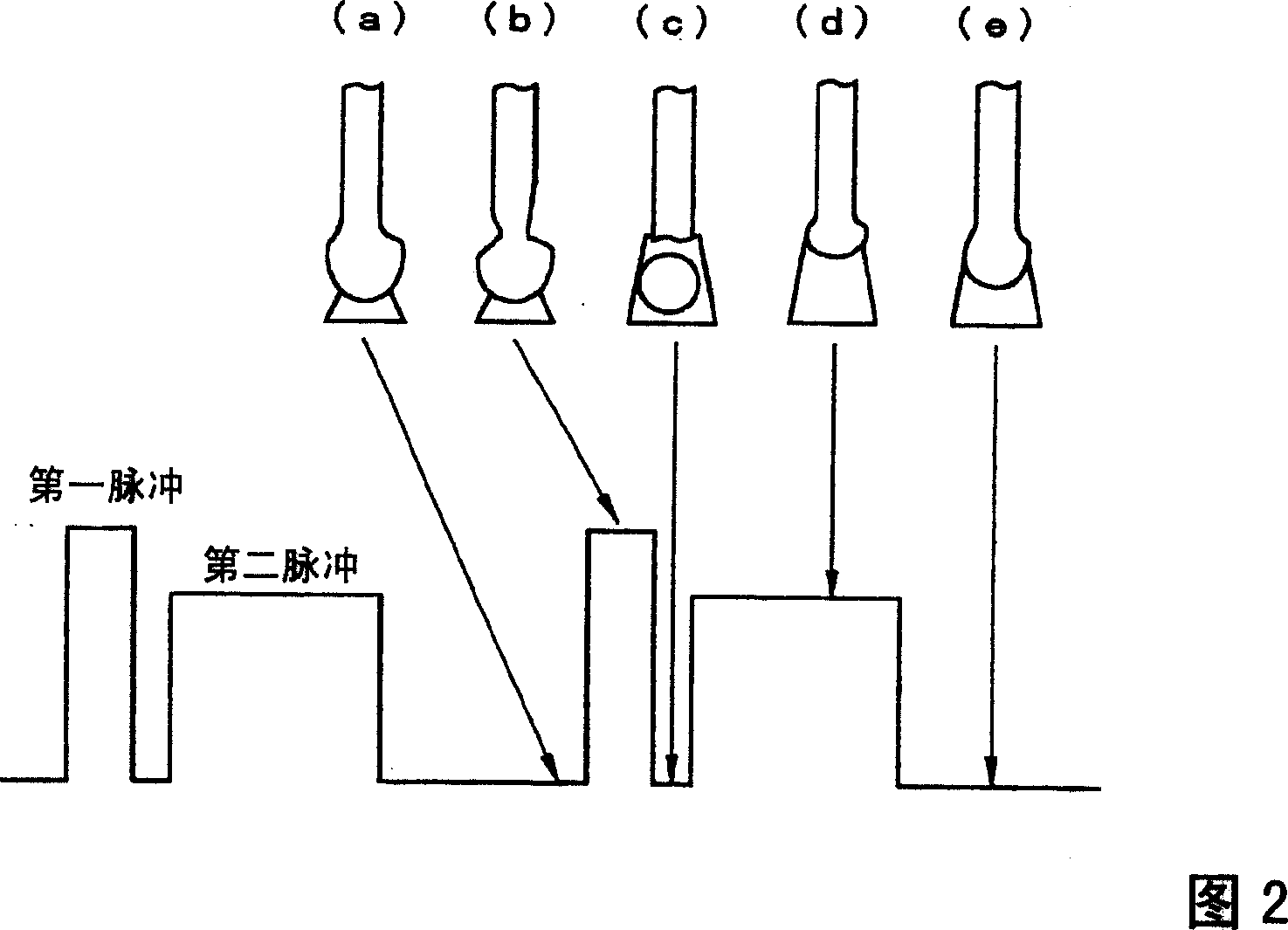
[0014] In addition, in Japanese Patent Application Laid-Open No. 10-263815, it is considered that spatter can be reduced by using a pulsed arc welding method that outputs two different pulse waveforms. The first pulse whose pulse period and base period are set shorter, and the second pulse whose pulse period is set shorter than the first pulse. If the first pulse period and the first base period are set, the droplet at the tip of the wire is not formed before receiving the electromagnetic contraction force brought by the second pulse, and the electromagnetic contraction force cannot effectively function
Regular transfer of one drop per cycle is difficult, and there is a problem that large-grain splashes occur

Method used


Image

  • Pulsed arc welding method
  • Pulsed arc welding method
  • Pulsed arc welding method

Examples


Embodiment 41

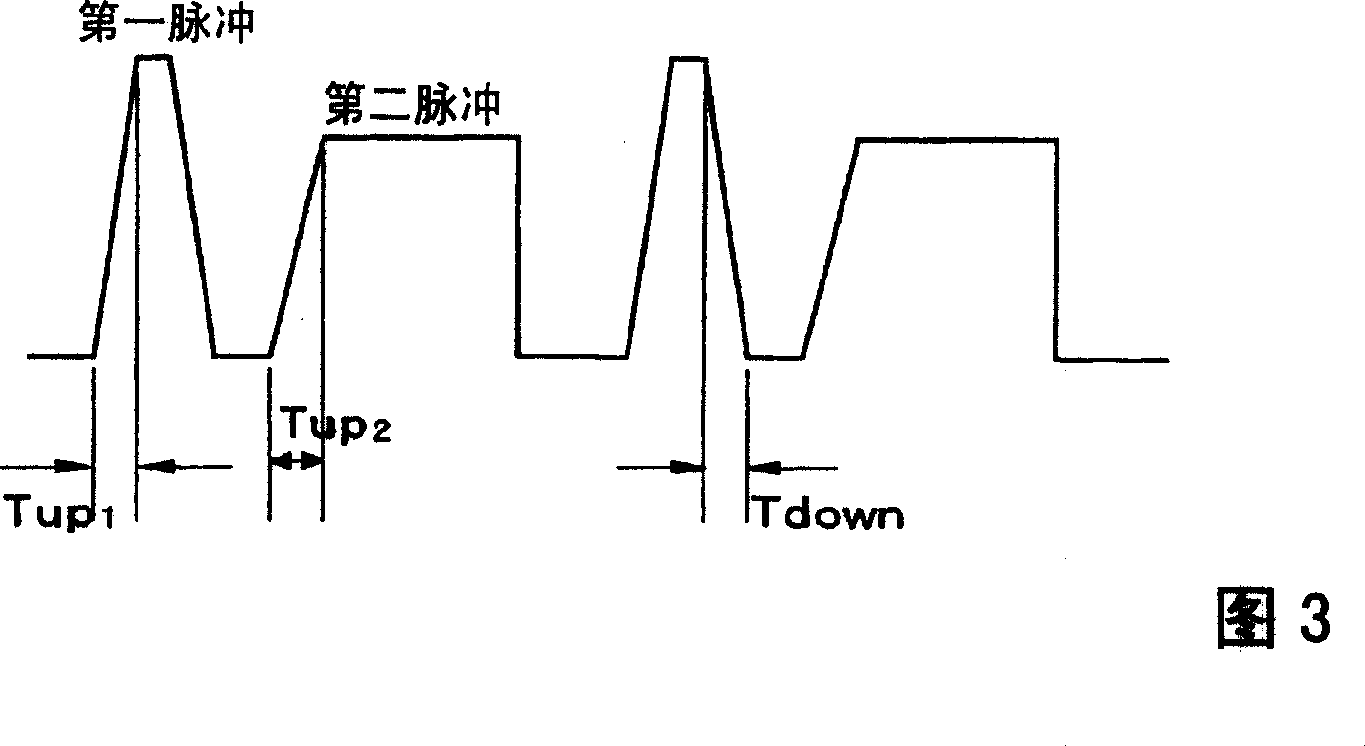
[0128] Examples 41 to 42 are examples of the third embodiment. In Example 41, the detection of droplet detachment was implemented. In Example 42, after setting the slope period during the first and second pulse rising periods and the first pulse falling period, it was implemented. Droplet detachment detection.

[0129] Examples 43 to 47 are examples of the third embodiment. Examples 43 to 44 overlap high-frequency pulses. Example 45 overlaps after setting a slope period during the rising period of the first and second pulses and during the falling period of the first pulse. In Example 47, droplet detachment detection was performed after the first and second pulse rising periods and the first pulse falling period provided a slope period, and high-frequency pulses were superimposed.

[0130] Next, comparative examples shown in Table 6 will be described. However, these Comparative Examples 48 to 61 satisfy the scope of the present invention. In Comparative Example 48, there is ...


PUM


Abstract

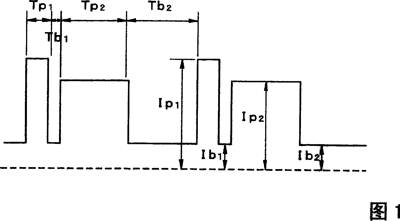
Disclosed is a pulsed arc welding method using a pulse current of alternately repeating first and second pulses as a weld current, wherein the first pulse and the second pulse have a pulse waveform of a different pulse peak current level and a different pulse width, respectively, and the following conditions are satisfied: peak current of the first pulse (Ip1)=300 to 700A; peak period (Tp1)=0.3 to 5.0 ms; base current Ib1=30 to 200A, base period (Tb1)=0.3 to 10 ms; peak current of the second pulse (Ip2)=200 to 600A; peak period (Tp2)=1.0 to 15 ms; base current (Ib2)=30 to 200A; and base period (Tb2)=3.0 to 20 ms. In this manner, the consumable electrode arc welding using carbon dioxide gas alone or a mixed gas made mainly of carbon dioxide gas as a shield gas can benefit from stabilized welding arc, improved regularity of droplet transfer, and significantly reduced generation rates of spatters and fumes.

Description

technical field [0001] The present invention relates to the pulse arc welding method that uses carbon dioxide alone or a mixed gas containing carbon dioxide as the main component as a shielding gas, and particularly relates to stabilizing the welding arc by implementing droplet transfer synchronous with the pulse, and can greatly reduce Pulse arc welding method for spatter generation and fume generation. Background technique [0002] With Ar-5~30%CO 2 The MAG welding method, which uses a mixed gas as a shielding gas, has been used in a wide range of fields because it can reduce the amount of spatter generated by making the molten droplets finer. Especially in the field where high-quality welding is required, the application of the pulsed MAG welding method that transfers one droplet to one pulse by outputting the welding current as a pulse current of about 100 to 350 IIz is expanding. [0003] However, Ar gas is more expensive than carbon dioxide, so carbon dioxide alone o...

Claims


Application Information

Patent Timeline
Patent Type & Authority Applications(China)
IPC IPC(8): B23K9/09B23K9/095B23K35/30B23K9/173B23K35/38
CPCB23K9/092B23K9/095B23K9/173B23K9/09
Inventor 舆石房树铃木启一山崎圭本间正浩
Owner KOBE STEEL LTD
Why Eureka
Try Eureka