Light voltage and wind power integrated networking device with the reactive power compensation and harmonious administration function
A harmonic control and functional technology, applied in reactive power compensation, harmonic reduction device, reactive power adjustment/elimination/compensation, etc., can solve the problems of slow development and high application cost
- Summary
- Abstract
- Description
- Claims
- Application Information
AI Technical Summary
Problems solved by technology
Method used
Image


Examples
Embodiment 1
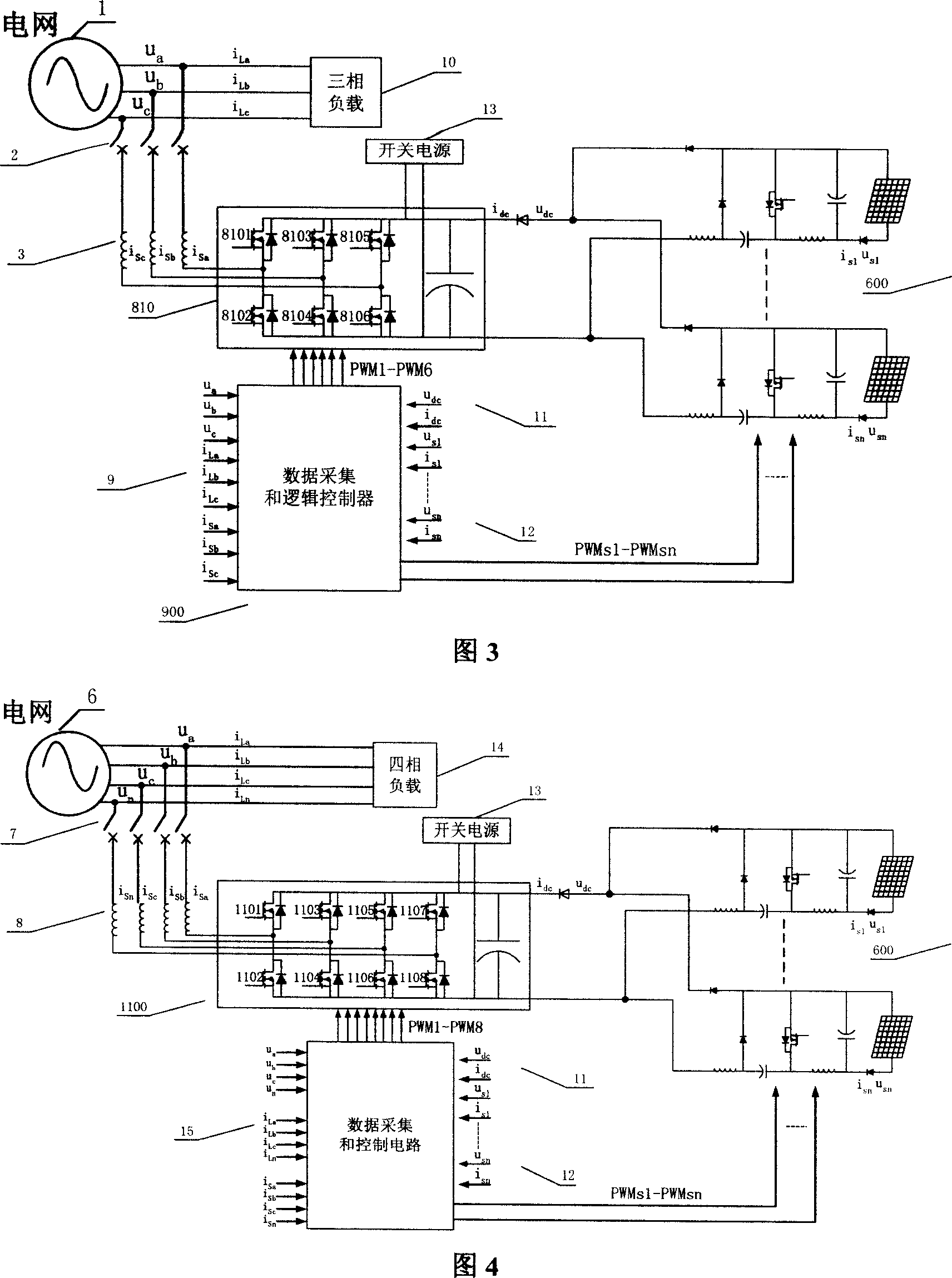
[0043] Example 1: Photovoltaic - two level - three phase or four phase
[0044] See accompanying drawings 3 and 4. The device consists of one or more groups of photovoltaic array power supplies, each group of photovoltaic array power supplies is connected to a type I power modulator, a DC bus link composed of electrolytic capacitor banks, a three-phase or four-phase two-level inverter 810, 1100, a three-phase or four-phase grid-connected reactor 3, 8, a three-phase or four-phase circuit breaker 2, 7, a data acquisition and logic controller 9, 15.
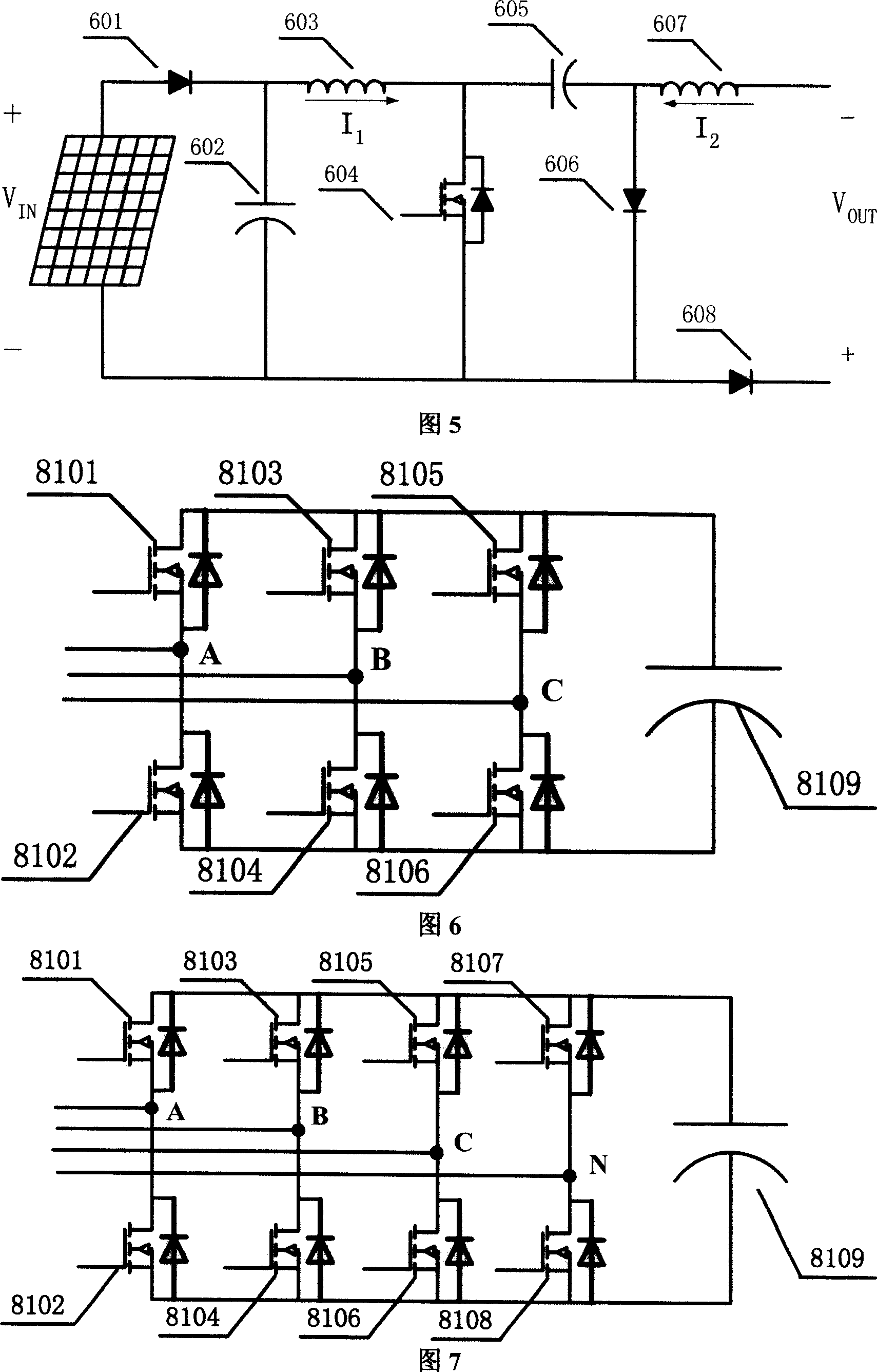
[0045] In the device, each photovoltaic array power supply is connected to a type I power modulator, and the output end of the power modulator is connected to the DC bus link. In the multi-power supply mode, each power supply and the power supply modulator are integrated 600 , and their outputs are connected in parallel to the DC bus link. The DC bus links are connected to the DC side of three-phase or four-phase two-level inverte...
Embodiment 2
[0054] Example 2: Photovoltaic-three-level-three-phase or four-phase
[0055] See accompanying drawings 8 and 9. Compared with Embodiment 1, the second embodiment of the present invention differs in that the three-phase or four-phase inverters are three-level structures 820 and 1200, as shown in Figure 10 and Figure 11 respectively. All the other parts are identical with embodiment 1.
Embodiment 3
[0056] Example 3: Wind power - two levels - three-phase or four-phase
[0057] See accompanying drawing 12, Fig. 13. The device consists of one or more groups of wind generators, each group of wind generators is connected to a type II power modulator, a DC bus link composed of electrolytic capacitor banks, and a three-phase or four-phase two-level inverter 810 , 1100, a three-phase or four-phase grid-connected reactor 3,8, a three-phase or four-phase circuit breaker 2,7, a data acquisition and logic controller 9,15.
[0058] In the device, each wind power generator power supply is connected to a type II power supply modulator, and the output end of the power supply modulator is connected to the DC bus link. In the multi-power supply mode, each power supply and the power supply modulator are integrated 700, and their outputs are connected in parallel Link with the DC bus. The DC bus links are connected to the DC side of the three-phase or four-phase two-level inverters 810 an...
PUM
 Abstract
Description
Claims
Application Information
 - R&D
- Intellectual Property
- Life Sciences
- Materials
- Tech Scout
- Unparalleled Data Quality
- Higher Quality Content
- 60% Fewer Hallucinations
Browse by: Latest US Patents, China's latest patents, Technical Efficacy Thesaurus, Application Domain, Technology Topic, Popular Technical Reports.
© 2025 PatSnap. All rights reserved.Legal|Privacy policy|Modern Slavery Act Transparency Statement|Sitemap|About US| Contact US: help@patsnap.com