Marking controller based on USB interface

A USB interface and controller technology, applied in typewriters, printing devices, digital output to printing units, etc., can solve the problems of increasing the volume of the control system, increasing the cost of the control system, and the limited storage capacity of the single-chip computer, and achieve the goal of increasing the marking speed Effect

Inactive Publication Date: 2007-08-15
HUAZHONG UNIV OF SCI & TECH
View PDF0 Cites 25 Cited by
  • Summary
  • Abstract
  • Description
  • Claims
  • Application Information

AI Technical Summary

Problems solved by technology

[0002] In the galvanometer scanning laser marking system, the hardware circuit of the control system is a control card designed based on the computer ISA bus or PCI bus. Stable operation will affect the stability of the marking system; the analog voltage signal output by the control card must be transmitted to the galvanometer control circuit through a long cable, and the strong electromagnetic interference generated by the laser power supply in the marking system It is easy to be introduced into the vibrating mirror control circuit through the transmission cable, affecting the normal operation of the vibrating mirror; the control card needs to be used with the computer, which increases the volume of the control system and increases the cost of the control system
There is also a laser marking controller controlled by a single-chip microcomputer, although it is separated from the ISA bus or PCI bus of the computer, but the storage capacity of the single-chip microcomputer is limited, and its interpolation operation speed is very slow, and only some simple interpolation algorithms can be performed. , so it is not possible to mark some complex patterns, its scope of use is limited, and the advantages of flexible use of laser marking cannot be fully utilized

Method used


Image

  • Marking controller based on USB interface
  • Marking controller based on USB interface
  • Marking controller based on USB interface

Examples


Embodiment Construction

[0026] The present invention is described below in conjunction with accompanying drawing.

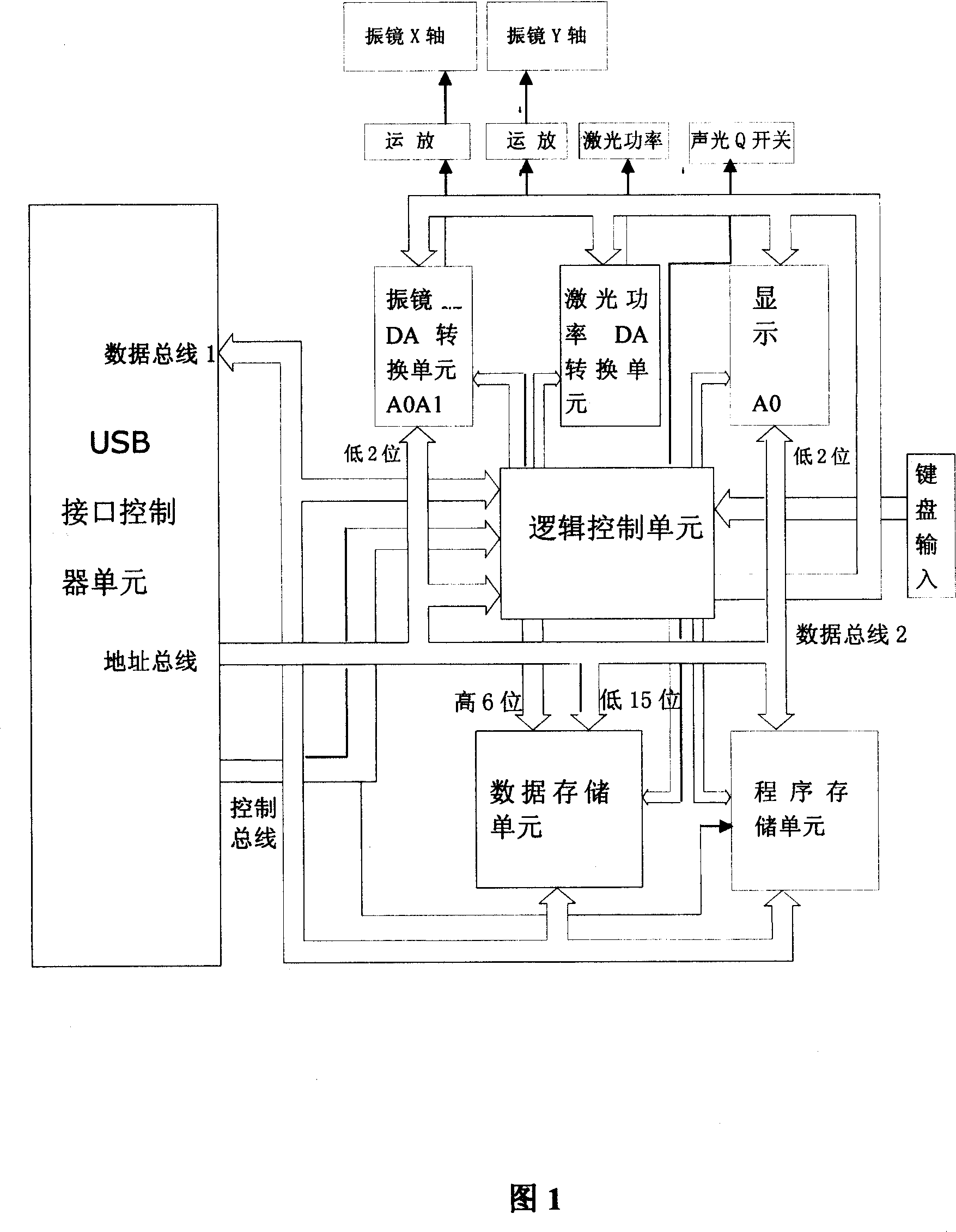
[0027] Fig. 1 is a general frame diagram of the present invention, including a USB interface controller unit, a data storage unit, a program storage unit, a D / A conversion unit, a logic control unit and a man-machine interface unit.

[0028] Below in conjunction with Fig. 2~Fig. 7, the present invention is described in detail through embodiment:

[0029] 1. USB interface controller unit

[0030] The USB interface controller unit circuit is shown in Figure 2, which consists of chips U1, U7, U8, U9, U10, sockets, jumpers J1, J2, J3, J5 and dial switch S4.

[0031] U1 chooses AN2131Q of EZ-USB series from Cypress Company as the USB interface controller. It is a full-speed USB interface controller chip that supports the USB1.1 specification and is the core of the entire circuit. It has 80 pins and independent 8-bit data The bus and 16-bit address bus are beneficial to the expansion of the...


PUM


Abstract

This invention relates to one target controller based on USB interface in laser marker controller, which comprises USB interface controller unit, data memory unit, program memory unit, D/A conversion unit, logic control unit and human to machine interface unit.

Description

technical field [0001] The invention belongs to a marking controller of a laser marking machine, in particular to a marking controller based on a USB interface of a universal serial bus. Background technique [0002] In the galvanometer scanning laser marking system, the hardware circuit of the control system is a control card designed based on the computer ISA bus or PCI bus. Stable operation will affect the stability of the marking system; the analog voltage signal output by the control card must be transmitted to the galvanometer control circuit through a long cable, and the strong electromagnetic interference generated by the laser power supply in the marking system It is easy to be introduced into the vibrating mirror control circuit through the transmission cable, affecting the normal operation of the vibrating mirror; the control card needs to be used together with the computer, which increases the volume and cost of the control system. There is also a laser marking ...

Claims


Application Information

Patent Timeline
Patent Type & Authority Applications(China)
IPC IPC(8): G06F3/12B41J3/00B41J29/38B41M5/24
Inventor 胡兵廖洪海应花山郭飞李洵
Owner HUAZHONG UNIV OF SCI & TECH
Why Eureka
Try Eureka