Durability testing stand of electric power-assisted steering system
An electric power steering, system life technology, applied in the direction of vehicle steering/jump performance, mechanical component testing, machine/structural component testing, etc. Achieve the effect of simplifying the structure, reducing the cost of manufacturing and testing
- Summary
- Abstract
- Description
- Claims
- Application Information
AI Technical Summary
Problems solved by technology
Method used
Image
Examples
Embodiment 1
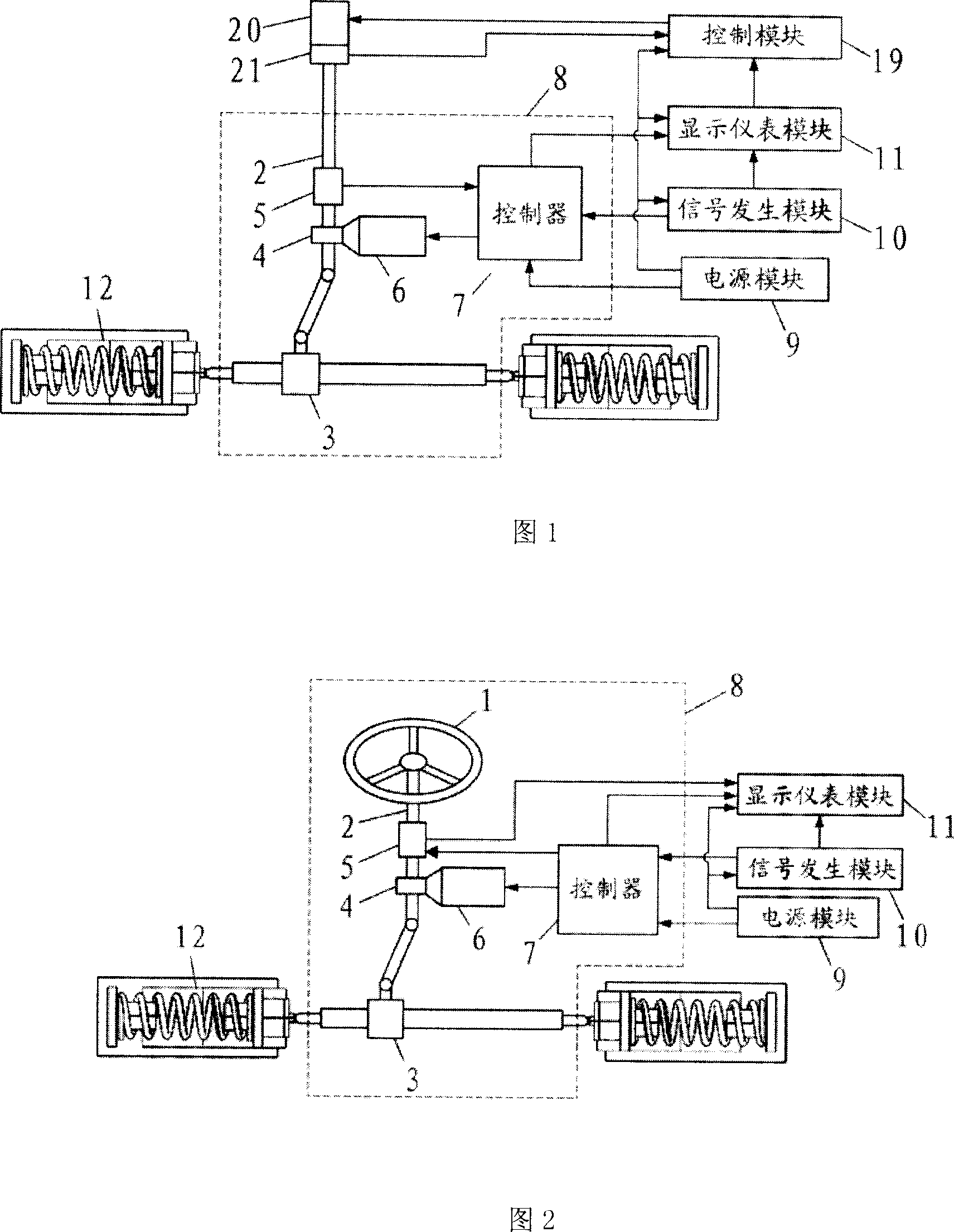
[0023] Referring to FIG. 2 , the EPS life test bench of the present invention is composed of a tested EPS sample 8 , a power supply module 9 , a signal generating module 10 , a display instrument module 11 , and a loading device 12 .
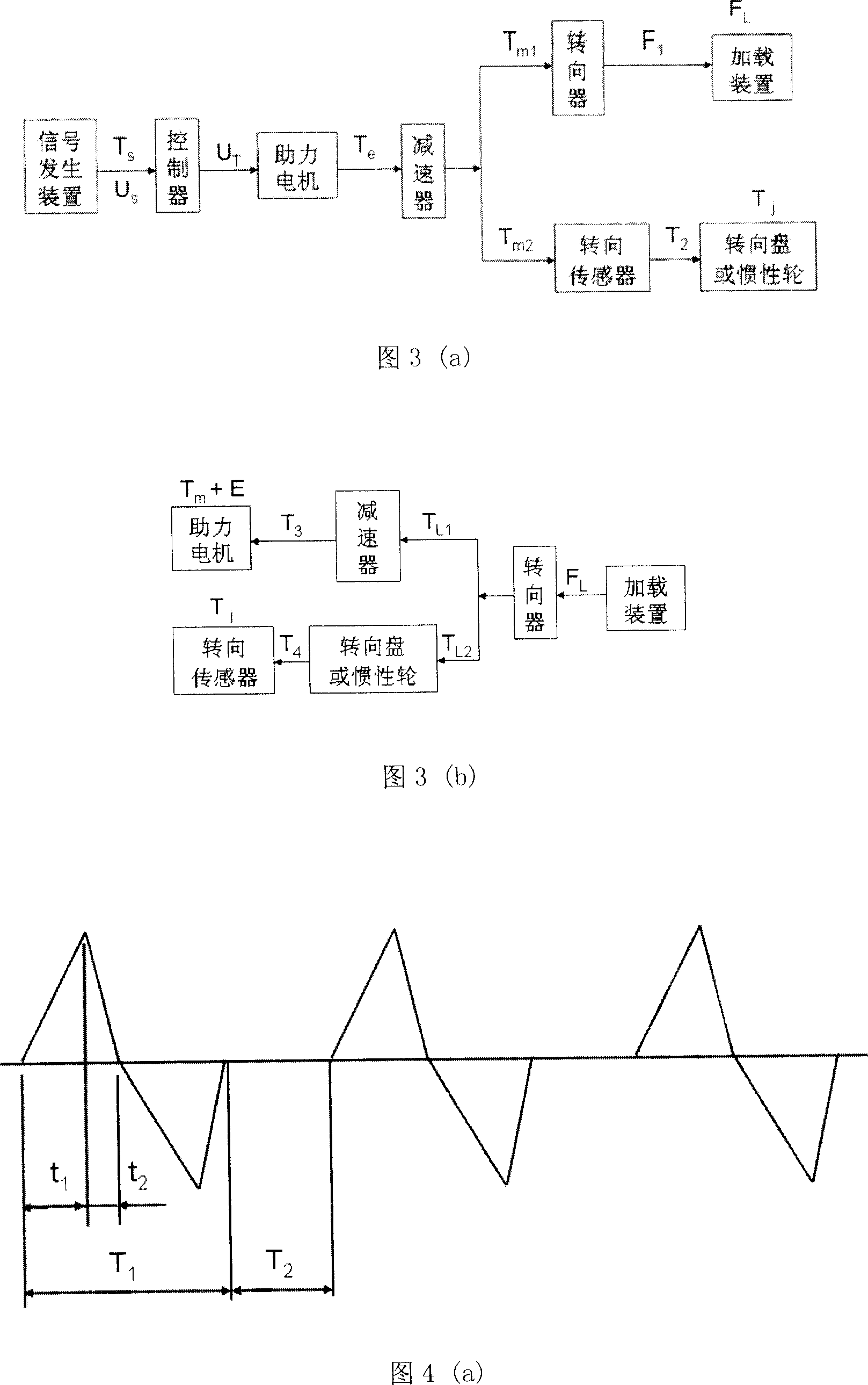
[0024] The EPS sample 8 under test in Fig. 2 comprises a steering wheel 1, a steering column 2, a steering gear 3, a speed reducer 4, a torque sensor 5, a motor assembly 6, a controller 7, etc., wherein the steering wheel (1), The steering column (2), the steering gear (3) and the like constitute a mechanical steering system. The output signal of the steering sensor 5 is directly connected to the display instrument module 11; the controller 7 transmits the voltage signal to the motor assembly 6, and at the same time provides working power to the steering sensor 5, and transmits the fault signal to the display instrument module 11; the motor assembly 6 is connected to the mechanical steering system through the reducer 4; the output end of the mec...
Embodiment 2
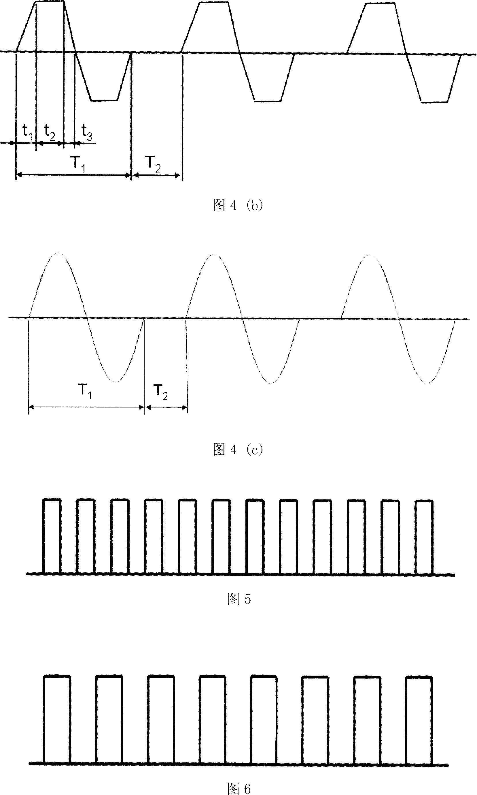
[0043] In order to make the cycle and amplitude of the steering wheel torque, vehicle speed, engine speed and other signals generated by the signal generating module 10 adjustable and convenient to meet the requirements of the variable working condition test, an industrial control computer and corresponding peripheral circuit boards can be used controller to generate the above signal. At the same time, through the preparation of corresponding data acquisition and processing software, the display will display the relevant test data and status. Figure 7(c) is a schematic diagram of the experimental parameter setting and data display of this method. The left half of the display 18 is a button for setting relevant parameters, including preset vehicle speed, engine speed, steering wheel torque signal type, period and amplitude, number of tests, etc. At the same time, there are related buttons for controlling the test process on the left half of the display 18. Through these button...
PUM
 Abstract
Description
Claims
Application Information
 - R&D
- Intellectual Property
- Life Sciences
- Materials
- Tech Scout
- Unparalleled Data Quality
- Higher Quality Content
- 60% Fewer Hallucinations
Browse by: Latest US Patents, China's latest patents, Technical Efficacy Thesaurus, Application Domain, Technology Topic, Popular Technical Reports.
© 2025 PatSnap. All rights reserved.Legal|Privacy policy|Modern Slavery Act Transparency Statement|Sitemap|About US| Contact US: help@patsnap.com


