Refrigerating device
A refrigeration device and refrigerant circuit technology, applied in refrigerators, refrigeration components, refrigeration and liquefaction, etc., can solve the problems of complicated refrigerant temperature control and so on
- Summary
- Abstract
- Description
- Claims
- Application Information
AI Technical Summary
Problems solved by technology
Method used
Image


Examples
Embodiment 1
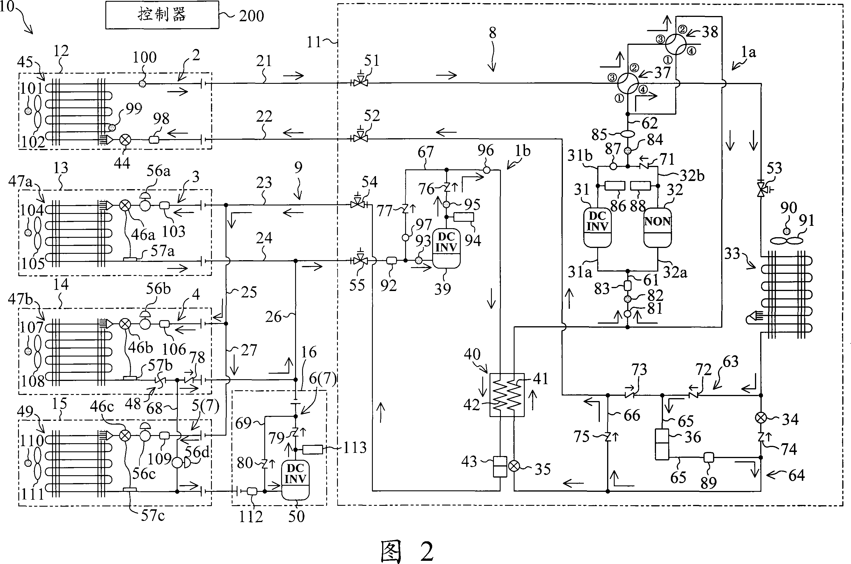
The refrigerating device (10) according to the first embodiment is installed in a convenience store or the like, and performs temperature adjustment in the store and cooling in a merchandise showcase at the same time. The refrigerating device (10) includes a high-stage refrigerant circuit (8) and a low-stage refrigerant circuit (9), and performs a binary refrigeration cycle.
[0046] As shown in Fig. 1, the freezing device (10) includes an outdoor unit (11), an air conditioning unit (12), first and second refrigeration units (13, 14), a refrigeration unit (15) and a pressurization unit (16). The outdoor unit (11) is set outdoors. And other units (12, 13, ...) are all arranged in stores such as convenience stores.
[0047] An outdoor unit (11) is provided with an outdoor circuit (1a) on the high section side and an outdoor circuit (1b) on the low section side. An air-conditioning circuit (2) is provided in the air-conditioning unit (12). First and second refrigeration circuit...
Embodiment 2
The configuration of the refrigerant circuit of the refrigeration system (10) according to the second embodiment is different from that of the refrigeration system according to the above-mentioned first embodiment. Only the points different from the first embodiment above will be described below.
[0139] As shown in Fig. 7, only one four-way reversing valve (37) is provided in the outdoor circuit (1a) on the high section side of the outdoor unit (11). The four-way reversing valve (37) is that the first port of the four-way reversing valve (37) is connected with the main discharge pipe (62), and the second port of the four-way reversing valve (37) is connected with the main suction pipe ( 61) connection, the third port of the four-way reversing valve (37) is connected to the first connecting pipe (21) through the first cut-off valve (51), the fourth port of the four-way reversing valve (37) is connected to the stage One end of the first heat exchange part (41) of the type heat...
Embodiment 3
The configuration of the refrigerant circuit of the refrigeration system (10) according to the third embodiment is different from that of the refrigeration system according to the above-mentioned first embodiment. Only the points different from the first embodiment above will be described below.
[0164] As shown in FIG. 11 , in the outdoor circuit ( 1 b ) on the low side of the outdoor unit ( 11 ), the difference from Embodiment 1 is that an outdoor heat exchanger ( 60 ) on the low side is provided. The outdoor heat exchanger (60) on the low stage side is connected in series with the second heat exchange part (42) of the cascade heat exchanger (40). In addition, the second heat exchange part (42) of the cascaded heat exchanger (40) is different from the second embodiment, and is arranged on the downstream side of the outdoor heat exchanger (60) on the lower stage side.
[0165] Specifically, one end of the low-stage outdoor heat exchanger (60) is connected to the fourth conne...
PUM
 Abstract
Description
Claims
Application Information
 - R&D
- Intellectual Property
- Life Sciences
- Materials
- Tech Scout
- Unparalleled Data Quality
- Higher Quality Content
- 60% Fewer Hallucinations
Browse by: Latest US Patents, China's latest patents, Technical Efficacy Thesaurus, Application Domain, Technology Topic, Popular Technical Reports.
© 2025 PatSnap. All rights reserved.Legal|Privacy policy|Modern Slavery Act Transparency Statement|Sitemap|About US| Contact US: help@patsnap.com