Method for configuring PMU taking regard of high risk cascading failure path
A cascading failure, high-risk technology, applied in emergency protection circuit devices, electrical components, information technology support systems, etc., can solve problems such as failure to consider, loss of network-wide observability, and inability to cope with the impact of multi-level cascading failures to ensure Observability, the effect of improving robustness
- Summary
- Abstract
- Description
- Claims
- Application Information
AI Technical Summary
Problems solved by technology
Method used
Image
Examples
Embodiment 1
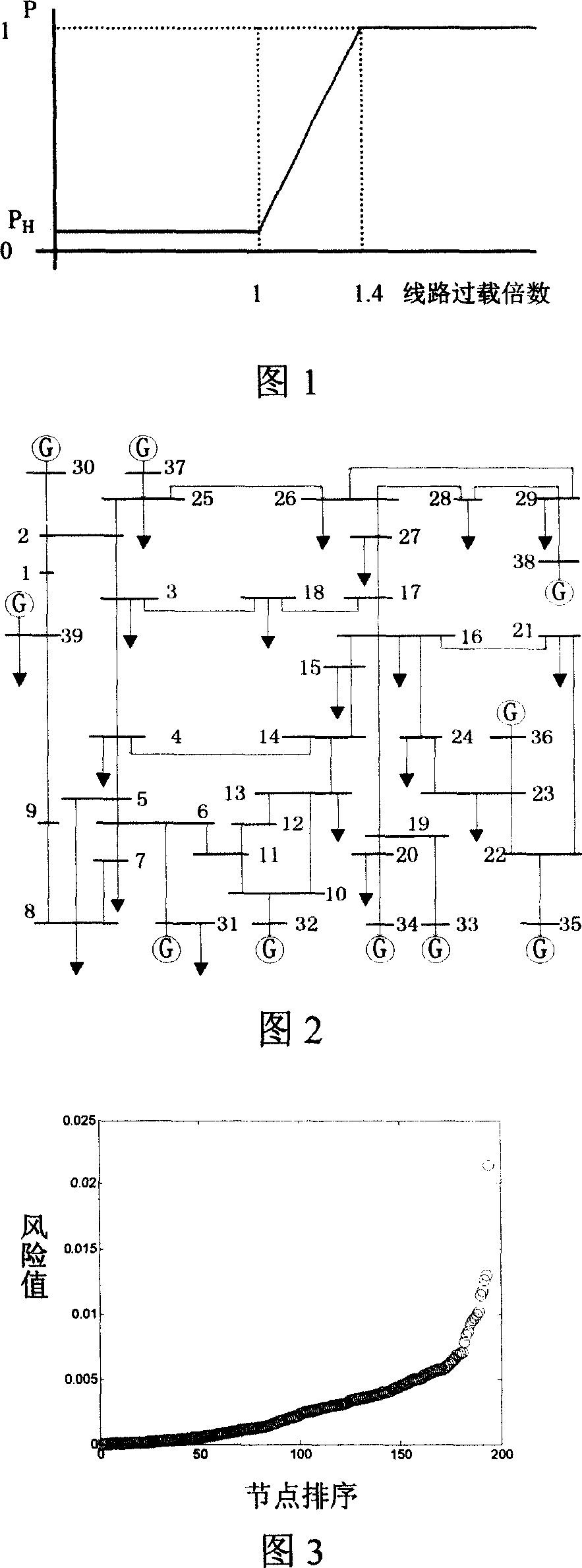
[0071] The cascading failure simulation experiment is carried out on the IEEE39 node system, as shown in Figure 3. A total of 280*46=12880 simulation experiments were carried out, that is, 280 simulation experiments were carried out with each line in the system as the initial fault. Each time the selected line is disconnected as the trigger of cascading failures, and then the hidden fault model is used to simulate the occurrence of cascading failures. After the cascading failures are over, the path of the cascading failures and the final load loss are recorded.
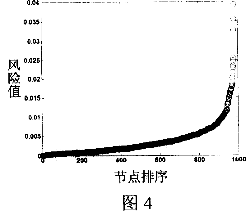
[0072] Analyze the cascading faults of level 2. Arrange all cascading failure paths from left to right according to the order of risk value from small to large, and the results are shown in Figure 4. It can be seen from the figure that the risk value of a small number of 2-level cascading failure paths is much higher than that of other paths. Select the top 8 paths with the risk value in the second-level cascading f...
Embodiment 2
[0079] The three-level cascading failure path in the IEEE39 node system is analyzed below. Experimental condition is the same as embodiment 1.
[0080]Analyze 3-level cascading failures. Arrange all cascading failure paths from left to right according to the order of risk value from small to large, and the results are shown in Figure 5. It can be seen from the figure that the risk value of a small number of 3-level cascading failure paths is much higher than that of other paths. Select the top 8 paths with the highest risk value among the 3-level cascading failure paths and list them in Table 3. Analyzing the influence of level 3 cascading failures on the observability of the system, it can be seen that 6 of the first 8 paths with the highest risk value of level 3 cascading failures will lead to incomplete observability of the system, and most of the paths will lead to unobservability of more than 2 nodes in the system .
[0081] Table 33 The 8 paths with the highest risk...
PUM
 Abstract
Description
Claims
Application Information
 - R&D
- Intellectual Property
- Life Sciences
- Materials
- Tech Scout
- Unparalleled Data Quality
- Higher Quality Content
- 60% Fewer Hallucinations
Browse by: Latest US Patents, China's latest patents, Technical Efficacy Thesaurus, Application Domain, Technology Topic, Popular Technical Reports.
© 2025 PatSnap. All rights reserved.Legal|Privacy policy|Modern Slavery Act Transparency Statement|Sitemap|About US| Contact US: help@patsnap.com


