Method for random error elimination in optical element interference sampling data

A technology of optical components and sampling data, applied in the direction of optical devices, optical instrument testing, machine/structural component testing, etc., can solve problems such as large errors, inability to provide accurate distribution of optical component surface errors, and ineffective effects

Inactive Publication Date: 2007-08-08
INST OF OPTICS & ELECTRONICS - CHINESE ACAD OF SCI
View PDF0 Cites 6 Cited by
  • Summary
  • Abstract
  • Description
  • Claims
  • Application Information

AI Technical Summary

Problems solved by technology

When using an interferometer to detect optical components, the inclination of the component when adjusting the optical path, the dust on the surface of the component, the influence of the environment (especially the vibration of the detection site) and other factors will bring errors to the measurement results
At present, in order to reduce the influence of airflow and vibration during interference, methods such as active anti-vibration interference technology are usually used to deal with it from the perspective of instrument design, but the effect is not obvious
[0003] At present, the surface quality evaluation indicators of optical components at home and abroad are mainly concentrated on the two indicators of peak-valley value and root mean square value, and the peak-valley value and root mean square value are calculated based on better measurement data from single or multiple measurement data value to evaluate the surface quality of optical components, but this method cannot provide the accurate distribution of the surface error of optical components, which brings confusion to the determination of the control model in the process
However, the number of rows and columns of the interferometer's multiple measurement data results has a certain difference. If the arithmetic mean is directly used for the surface shape distribution of large-aperture optical elements, it will bring a large error.
Therefore, how to unify the coordinate positions of multiple measurement data and use its arithmetic mean to eliminate the influence of random errors is still blank

Method used


Image

  • Method for random error elimination in optical element interference sampling data
  • Method for random error elimination in optical element interference sampling data

Examples


Embodiment 1

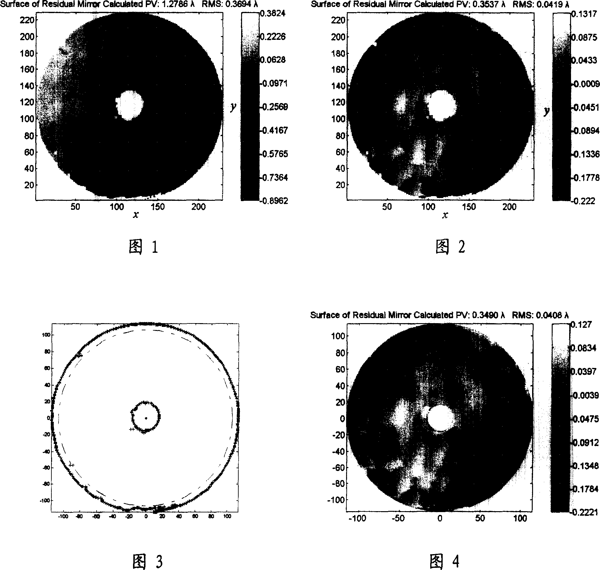
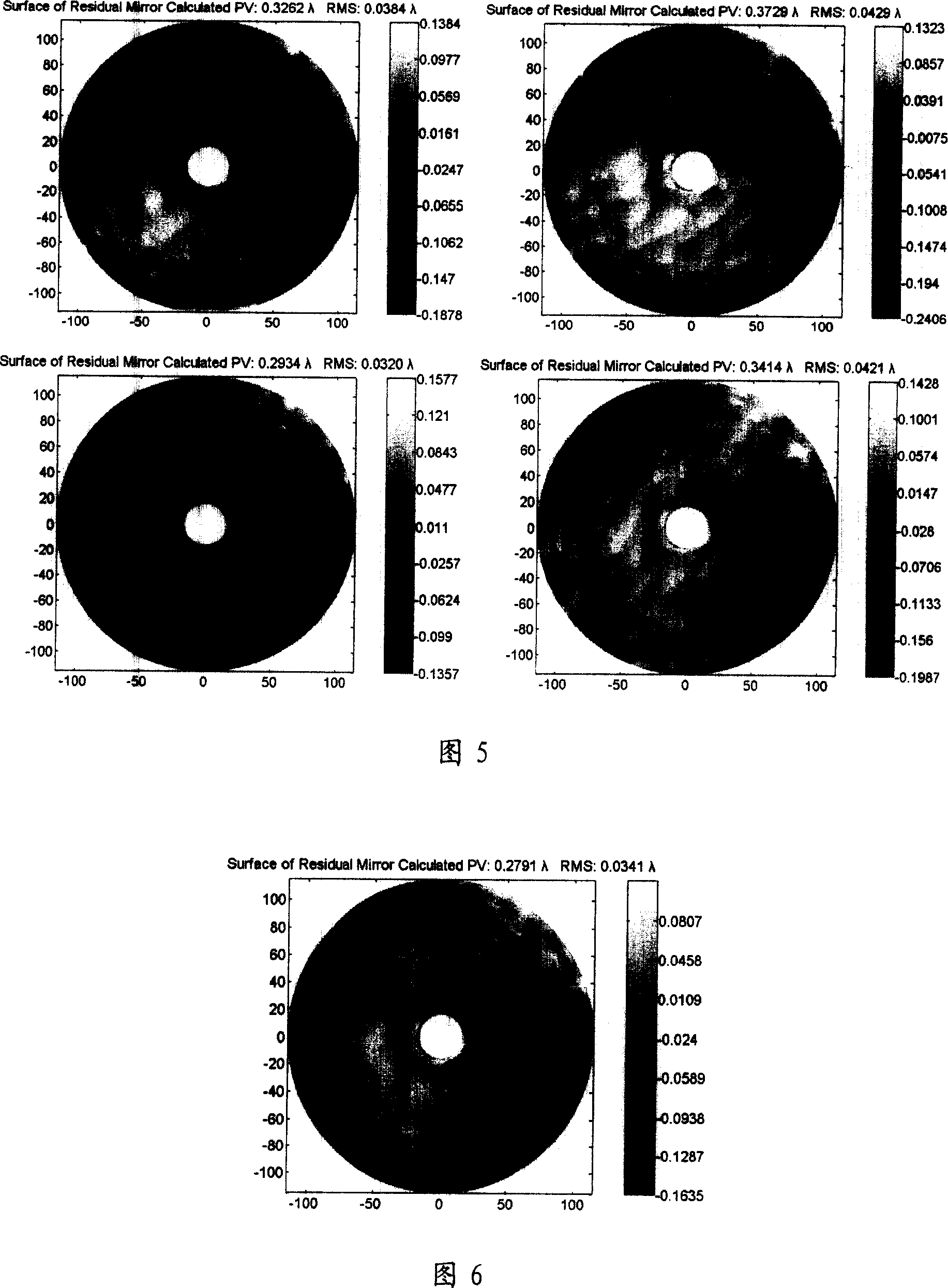
[0039] Embodiment 1, the analysis process of eliminating the random error in the optical element interference sampling data when detecting the aspherical mirror with a diameter of =1200mm by the method of the present invention:

[0040] ① Obtain the surface shape data of the inspected circular aperture optical element through the interferometer, use the length measurement tool to determine the measured range of the inspected optical element, and give the x and y directions in the interferogram, as shown in Figure 1. ;

[0041] ②Use the least square method to eliminate the tilt term and constant term from the surface data of the optical element;

[0042] The elimination of the oblique term and constant term of the surface shape data of the optical element can be linearly fitted to the measured data through the linear fitting function y=ax+b. According to the least square fitting method, the normal equation can be solved by:

[0043] ma ...


PUM


Abstract

A method to eliminate the random error in the sampling data of the optical component interference, relates to an improvement for the circular aperture optical component surface error detection method. It uses the information technology to process the optics component surface detection data acquired by the interferometer, and uses the improved least squares method to confirm the data central location, and according to the error theory, processing the multiple detection data, to eliminate the random error effect, and finally confirming the optics component surface. Through the research of multiple random errors interference data acquired by the scene, the invention provides a new method to eliminate random error effect in the optical component surface detection, and it is of great application value to the high-quality optical component detection and processing.

Description

technical field [0001] The invention relates to a method for eliminating random errors in interference sampling data of optical elements, belonging to the field of optical testing. Background technique [0002] In precision optical systems, the surface quality of optical components has attracted more and more attention, and it is necessary to accurately measure the surface shape of the components. When using an interferometer to detect optical components, the tilt of the component when adjusting the optical path, the dust on the surface of the component, the influence of the environment (especially the vibration of the detection site) and other factors will bring errors to the measurement results. At present, in order to reduce the impact of airflow and vibration during interference, methods such as active anti-vibration interference technology are usually used to deal with it from the perspective of instrument design, but the effect is not obvious. [0003] At present, the...

Claims


Application Information

Patent Timeline
Patent Type & Authority Applications(China)
IPC IPC(8): G01B9/02G01B11/00G01M11/00
Inventor 陈伟姚汉民伍凡范斌万勇建朋汉林
Owner INST OF OPTICS & ELECTRONICS - CHINESE ACAD OF SCI
Why Eureka
Try Eureka