
System and method for controlling rotational speed of fan

A technology of fan speed and control system, applied in the direction of speed/acceleration control without auxiliary power, auxiliary non-electric temperature control, etc., can solve the problems of loss of fan life, sudden change of speed, etc., to prolong fan life and smooth fan operation. , The effect of reducing system ambient noise

Inactive Publication Date: 2007-08-01
INVENTEC CORP
View PDF0 Cites 23 Cited by
  • Summary
  • Abstract
  • Description
  • Claims
  • Application Information

AI Technical Summary

Problems solved by technology

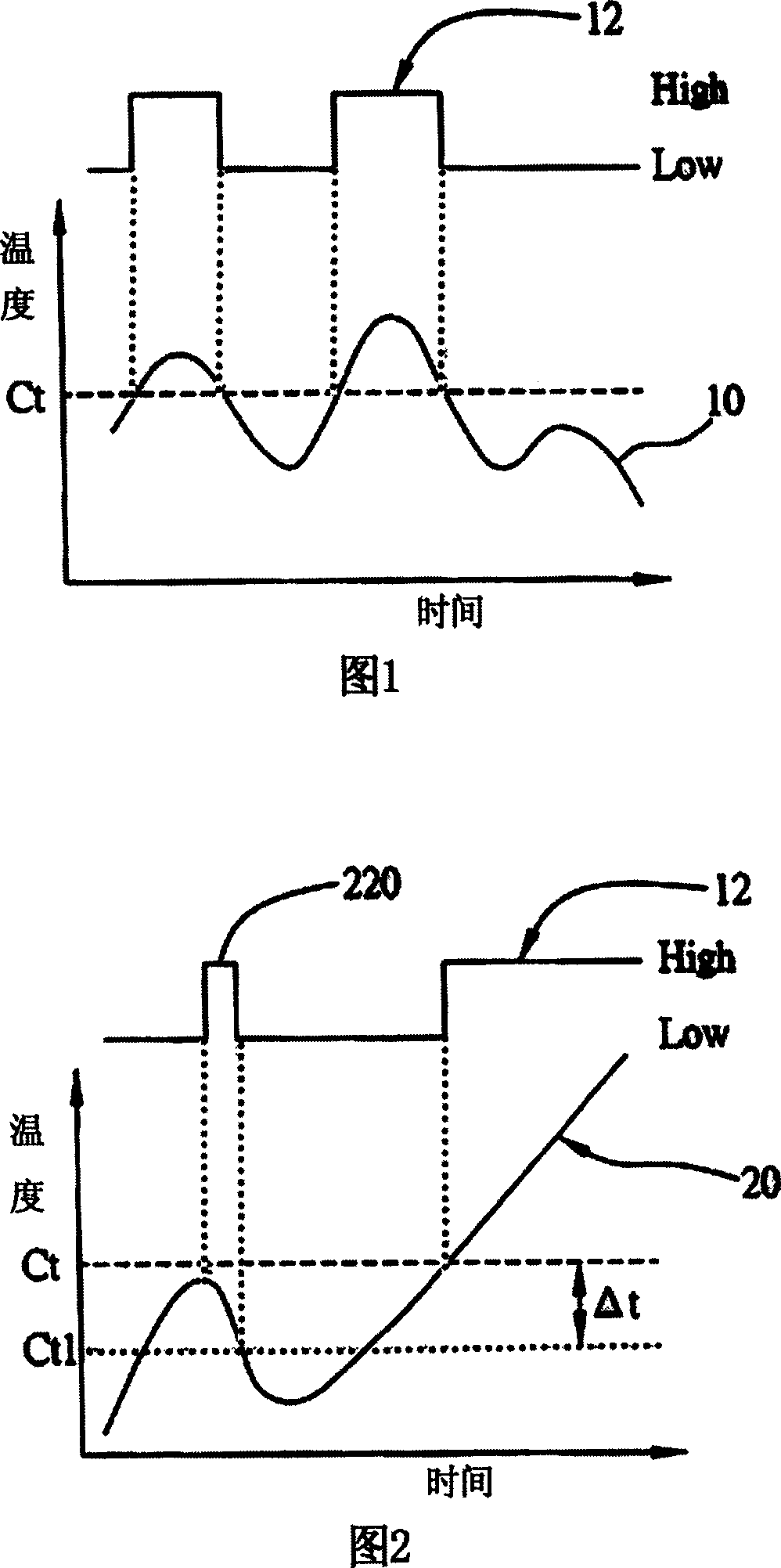
After adding the temperature change Δt, the fan can maintain stability for a long time, but this method cannot completely solve the problem of frequent changes in the speed caused by temperature oscillations
As shown in the figure, when the system temperature change curve 20 is at the critical temperature value Ct 1 When the vibration is nearby, the fan speed will still be adjusted, forming the fan speed change line 22 and causing a sudden change in the speed 220 at the corresponding position, which seriously reduces the life of the fan

Method used


Image

  • System and method for controlling  rotational speed of fan
  • System and method for controlling  rotational speed of fan

Examples


Embodiment

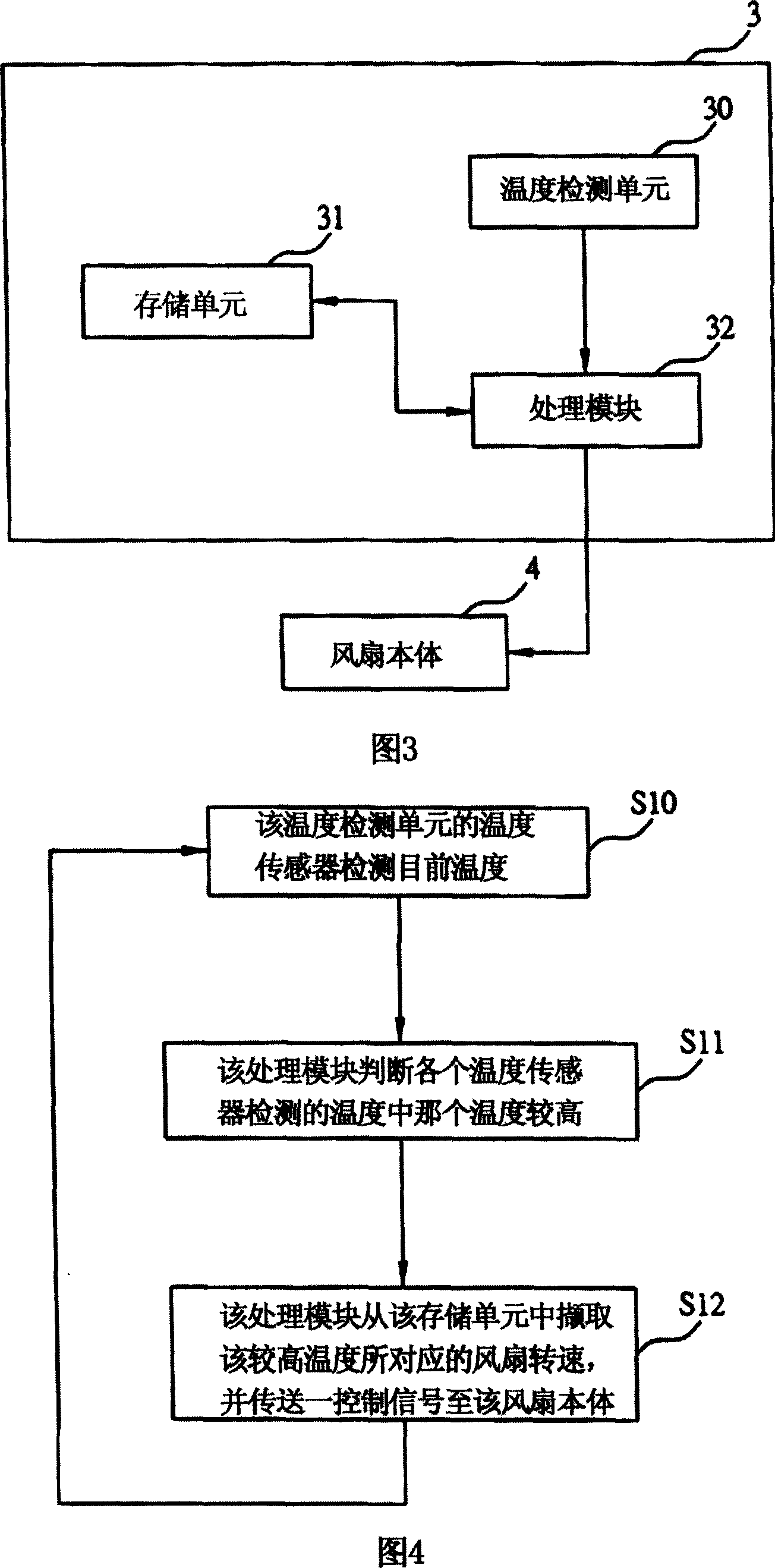
[0017] FIG. 3 is a schematic block diagram of the basic structure of the fan speed control system of the present invention. As shown in the figure, the fan speed control system 3 at least includes a temperature detection unit 30 , a storage unit 31 and a processing module 32 connected to the fan body 4 . The fan speed control system 3 is set in an electronic device that uses a fan to dissipate heat, and is used to adjust the ambient temperature of the system. In this embodiment, the electronic device is, for example, a server.

[0018] The temperature detection unit 30 has a plurality of sensors, and after the fan adjusts the temperature of different heating objects (such as the central processing unit and other functional chips, etc.), it detects the temperature of the heating objects and outputs the detected temperature. The plurality of sensors sense the system environment temperature in real time under the operating condition of the server, and transmit the system temperat...


PUM


Abstract

This invention discloses one fan rotation control system and method applied in electrode device with fan temperature adjust, wherein, the system comprises the following parts: temperature test unit with multiple sensors to test different heat object temperature for output; memory unit to store temperature and rotation speed relationship to make the preset temperature respond one preset rotation and process module; catching temperature fan rotation according to the output temperature; sending one control signal to one fan.

Description

technical field [0001] The present invention relates to a fan speed control system and method, in particular to a fan speed control system and method in which the fan speed changes linearly. Background technique [0002] With the rapid development of computer technology, computers have become an indispensable tool in people's daily life and work. Due to the continuous improvement of computer performance, the processing performed has become more complex, and the calculation speed of the central processing unit has also increased relatively. The central processing unit will generate a lot of heat under high-speed calculations, which will affect the system. In the lightest cases, it may cause the system to crash, or even cause irreversible damage to the system. Therefore, people are paying more and more attention to the research on system heat dissipation. . [0003] Air-cooled heat dissipation is the most common heat dissipation method in the industry. Fans and heat sinks for...

Claims


Application Information

Patent Timeline
IPC IPC(8): G05D13/16G05D23/185
Inventor 沈嘉荣黄闵宗
Owner INVENTEC CORP
Learn More