
Joint coding and decoding device and method for source channel

A codec method and encoder technology, applied in baseband systems, digital transmission systems, electrical components, etc., can solve the problems of codec complexity, low channel resource utilization, lack of practicability, etc., and achieve low codec delay , high encoding rate, low complexity effect

Inactive Publication Date: 2007-07-25
BEIHANG UNIV
View PDF0 Cites 12 Cited by
  • Summary
  • Abstract
  • Description
  • Claims
  • Application Information

AI Technical Summary

Problems solved by technology

[0003] The simplification and convenience brought by the separation design of the communication system objectively promote the development and application of the separation structure communication system, but at the same time it also brings some unavoidable inherent disadvantages: First, from the perspective of feasibility, the separation communication system requires The overall optimality is achieved under the condition that the codec has infinite complexity and delay, which is unacceptable for real-time communication; second, the theory is no longer valid for non-ergodic and multi-user systems, that is, in these cases In this case, there is no longer a separate optimal system; third, after the channel quality drops to a certain threshold, the system immediately collapses (break down), that is, there is a threshold effect. At this time, the channel coding can no longer correct errors, so the separation system Lack of robustness to variable channels; Fourth, the separation system cannot improve the communication quality when the channel quality is improved relative to the design channel conditions, so the utilization rate of channel resources is low
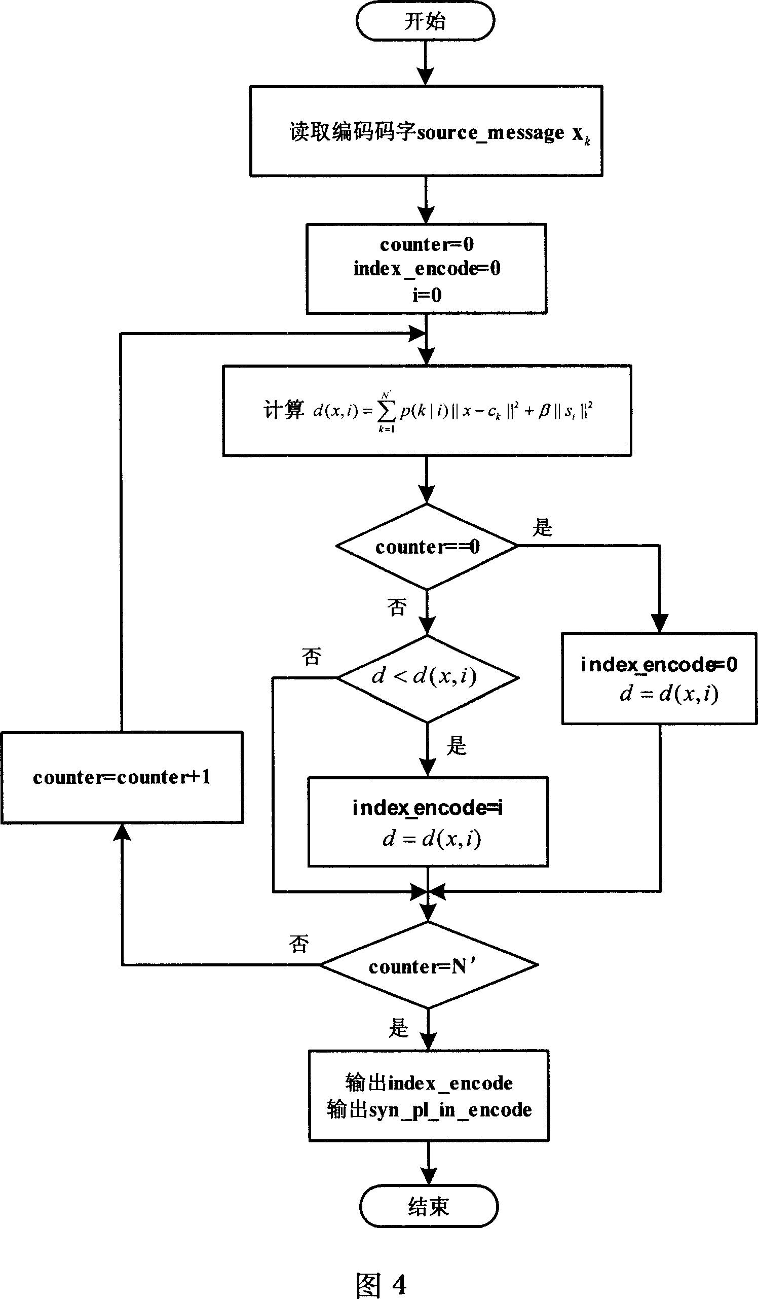
Although the suboptimal Shannon direct source channel mapper for a specific source and channel characteristics can be obtained by using the power-limited channel optimization vector quantization iterative algorithm, the transmit power is not controllable at this time, specifically, although the optimization design process considers The power limit of the channel, but the encoder transmit power obtained by iterative optimization cannot guarantee to strictly meet the transmit power requirements, so it lacks practicability

Method used


Image

  • Joint coding and decoding device and method for source channel
  • Joint coding and decoding device and method for source channel
  • Joint coding and decoding device and method for source channel

Examples


Embodiment Construction

[0027] The present invention will be further described below in conjunction with the accompanying drawings.

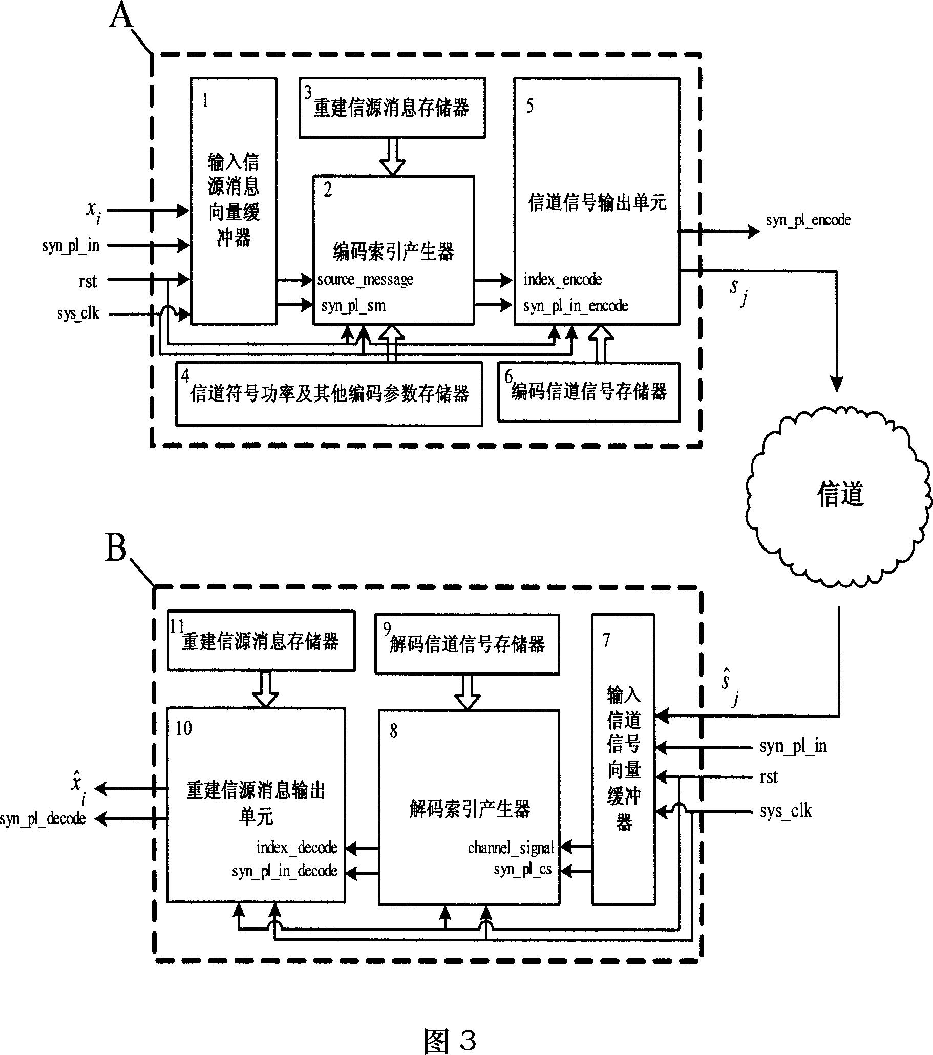
[0028] Encoder A of the present invention as shown in Figure 3, its main part is mainly by input source message vector buffer 1, encoding index generator 2, reconstruction source message memory 3, channel signal power and other encoding parameter memory 4, channel The signal output unit 5 and the coded channel signal memory 6 constitute. The input to the entire encoder consists of the source message sample serial input x i , input synchronization pulse syn_pl_in, system reset signal rst, system clock sys_clk, wherein system reset signal rst and system clock sys_clk are also connected to encoding index generator 2 and channel signal output unit 5 for system reset and drive clock; encoder output includes Channel signal serial output sj and encoding output synchronous pulse signal syn_pl_encode. When the rst reset signal is valid, the encoder A is reset, and then the en...


PUM


Abstract

In the invention, the codec is divided into two parts-encoder and decoder. The encoder comprises: a vector buffer of the inputted message source, an encode index generator; a channel signal outputting unit; a channel signal power and parameter memory; a re-built message source memory; and an encoding channel signal memory. The decoder comprises: a vector buffer of the inputted channel, a decode index generator, a re-built message source outputting unit; a decode channel signal memory and a re-built message source memory. The codec provided can the channel-optimized k-dimension channel signals from L-dimension message source after direct coding so as to implement the bandwidth compression and expansion of message source.

Description

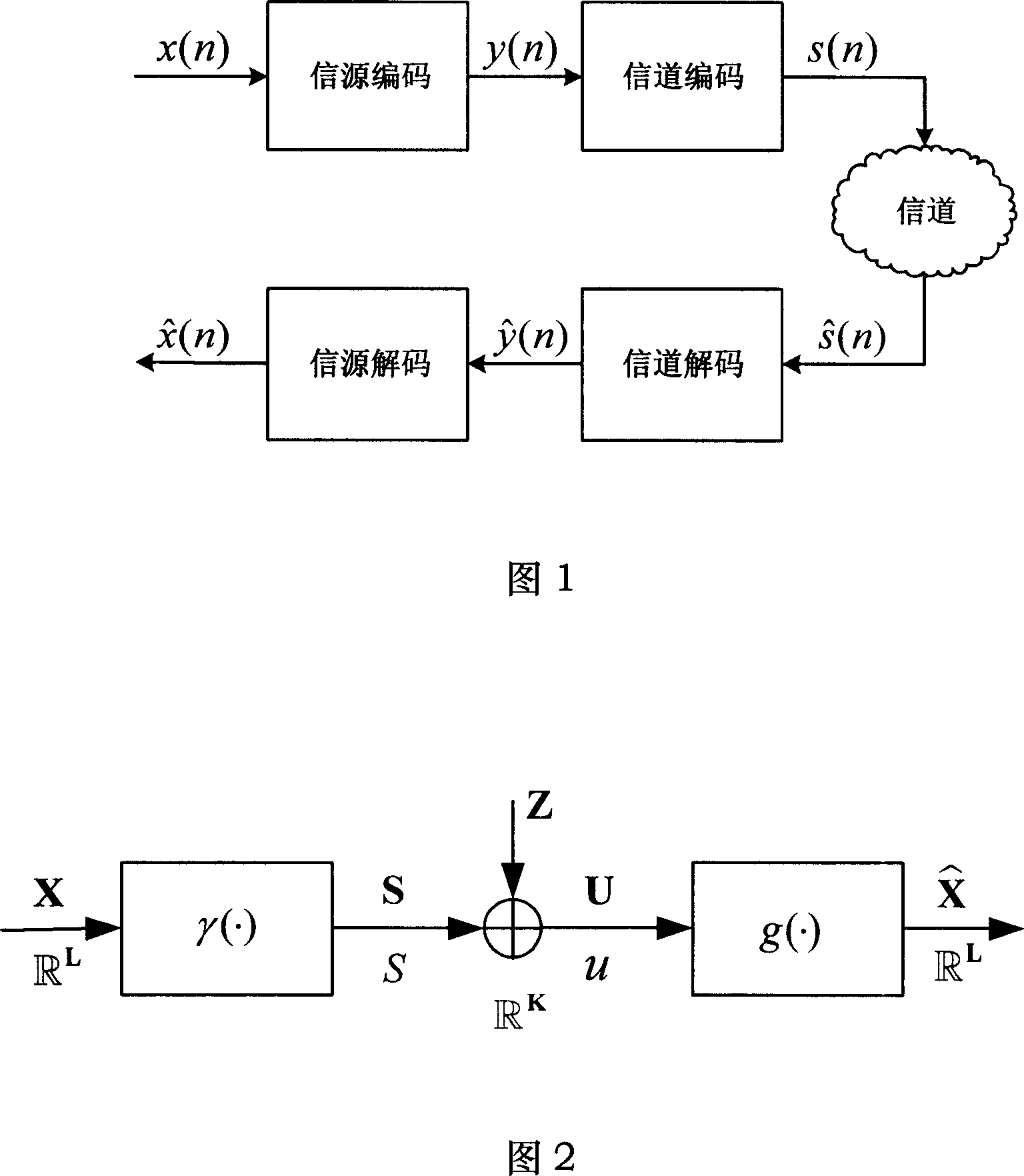
technical field [0001] The invention belongs to the communication field, and in particular relates to an information source channel codec and a codec method. Background technique [0002] At present, most of the communication systems are established under the framework of the separation structure communication system based on Shannon's separation theory. As shown in Figure 1, it is a general model of a communication system with a separated structure: from the source to the sink, it is divided into five parts: source coding, channel coding, channel, channel decoding, and source decoding. [0003] The simplification and convenience brought by the separation design of the communication system objectively promote the development and application of the separation structure communication system, but at the same time it also brings some unavoidable inherent disadvantages: First, from the perspective of feasibility, the separation communication system requires The overall optimalit...

Claims


Application Information

Patent Timeline
IPC IPC(8): H04L25/00H04L25/02
Inventor 张晓林王哲
Owner BEIHANG UNIV
Learn More