Stator of multipole internal rotor permanent magnet generator

A permanent magnet generator and rotor-type technology, which is applied in the manufacture of stator/rotor bodies, magnetic circuits, electrical components, etc., can solve the problems of miniaturization, light weight and thinning, and the inability to make large power and parts Many problems, to achieve the effect of weight reduction, easy installation, and simplified structure

Inactive Publication Date: 2007-07-25
WUXI KIPOR POWER CO LTD
View PDF1 Cites 2 Cited by
  • Summary
  • Abstract
  • Description
  • Claims
  • Application Information

AI Technical Summary

Problems solved by technology

[0003] The stator structure of the generator disclosed above has many parts, complex structure or needs to be installed in the casing. It is difficult to achieve miniaturization, light weight and thinning of this structure.
And such a structure cannot be made into a higher power, it is only used in a small power range

Method used


Image

  • Stator of multipole internal rotor permanent magnet generator
  • Stator of multipole internal rotor permanent magnet generator
  • Stator of multipole internal rotor permanent magnet generator

Examples


Embodiment Construction

[0020] Below the present invention will be further described in conjunction with the embodiment in the accompanying drawing:

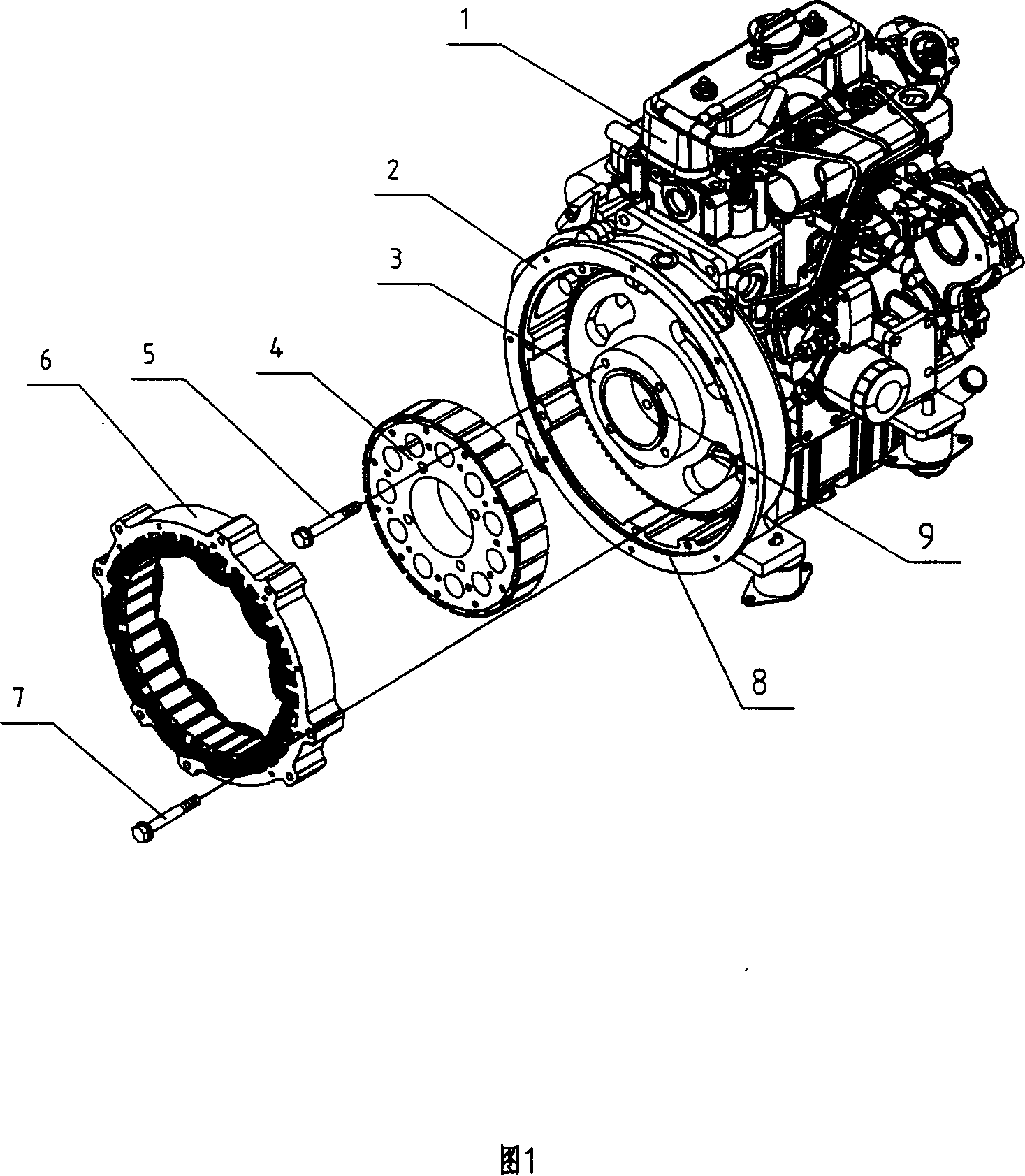
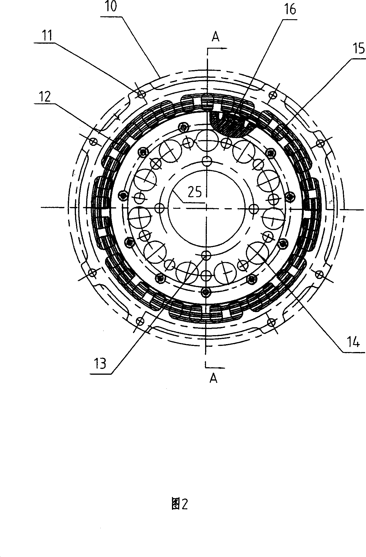
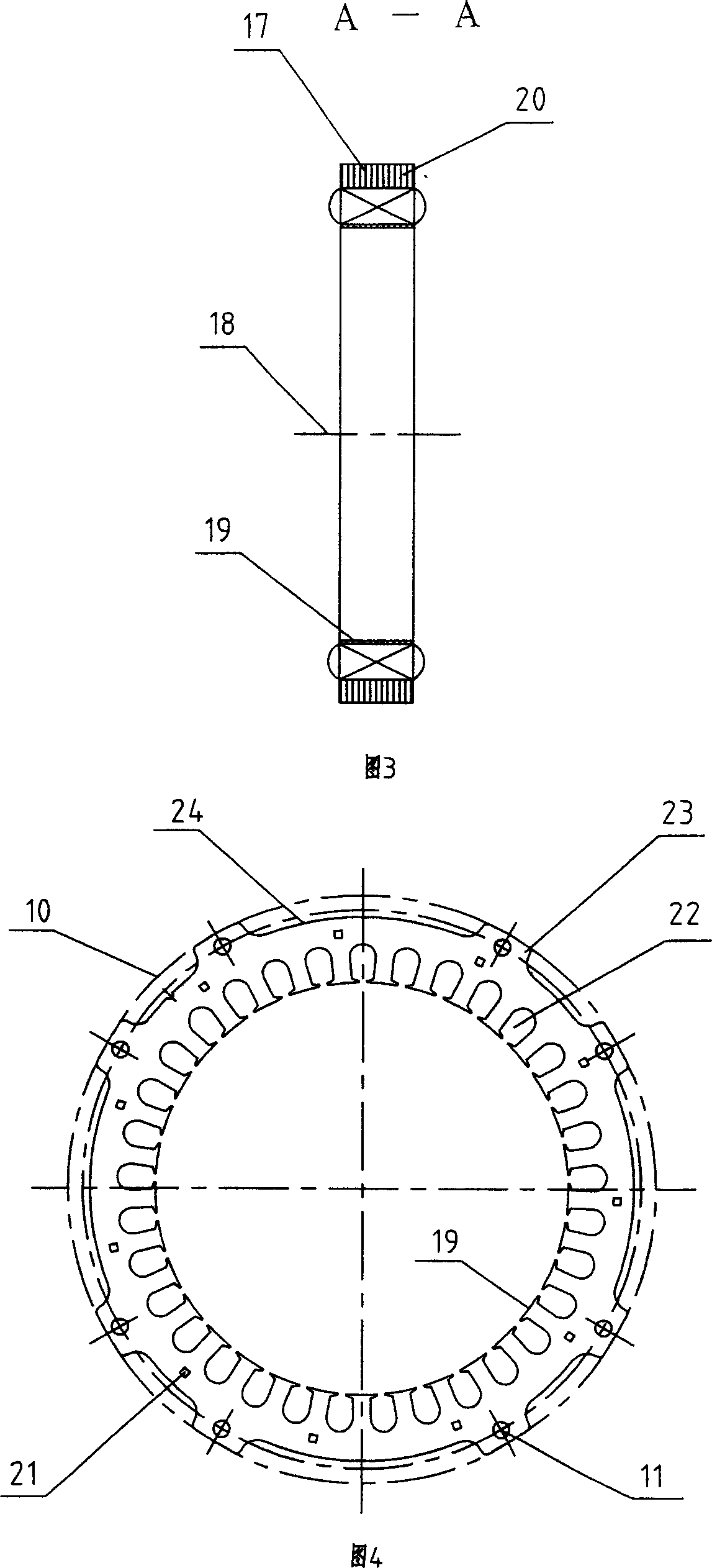
[0021] This embodiment is mainly composed of engine assembly 1, stator seat 2, rotor seat 3, rotor assembly 4, bolt 5, stator assembly 6, bolt 7, stator seat positioning opening 8, rotor seat positioning opening 9, stator positioning circle 10 , stator bolt hole 11, stator winding 12, rotor bolt hole 13, insert piece 15, permanent magnet 16, stator body 17, stator body rotation center 18, stator inner hole 19, stator punching sheet 20, stator self-locking slot 21, stator Wire groove 22, stator boss 23, stator groove 24, positioning circle 25 etc. are formed in the rotor. As shown in Figures 1 and 2: the stator assembly 6 of the present invention and the rotor assembly 4 comprising permanent magnets 16 form a generator, and the generator and an engine assembly 1 form a generator set. The stator assembly 6 of the present invention is composed of a stato...


PUM


Abstract

Through self-buckling slot for stator, punch pieces of stator are stacked to form stator body. Neck groove of stator are prepared on inner side face of stator faced to rotor. Number of the neck groove is equal to number of permanent magnet taken in by rotor. Multiple stator windings are inserted in neck groove. Characters are that boltholes are setup on stator in direction parallel to line of rotation axis. Through the boltholes, one end face of stator is fixed on stator seat of engine assembly directly. The invention realizes high output efficiency, and high output power, easy to produce generator with larger power, as well as stability, durability, and reliability. Features are: no chassis, simple structure, compact, thin, light weight, and miniaturization.

Description

technical field [0001] The invention relates to a stator of a multi-pole inner rotor type permanent magnet generator, in particular to a generator suitable for miniaturization, light weight and thinning, and belongs to the technical field of generators. Background technique [0002] Before the disclosure of the present invention, in the known technology, the stator of the permanent magnet generator was also disclosed. For example, a motor generator disclosed in PCT / US2004 / 015485 includes a motor generator with a plurality of permanent magnet elements. The rotor, these permanent magnets are arranged in a circular ring structure around the axis of rotation, the magnet elements are continuously alternating in magnetic polarity along the surface of the inner ring, and the stator is separated from the rotor by a radial air gap, and the stator includes a plurality of magnetic core segments , the core segments have respective coils wound thereon to form stator windings, each stator...

Claims


Application Information

Patent Timeline
IPC IPC(8): H02K1/16H02K3/28H02K15/02
CPCH02K1/185H02K7/1815
Inventor 肖亨琳
Owner WUXI KIPOR POWER CO LTD
Why Eureka
Try Eureka