Air bag lid
An airbag and cover technology, which is applied in vehicle safety arrangement, pedestrian/passenger safety arrangement, transportation and packaging, etc., can solve problems such as fracture extension to undesired areas and fracture dispersion, so as to avoid unnecessary diffusion and restrain The effect of deformation expansion
- Summary
- Abstract
- Description
- Claims
- Application Information
AI Technical Summary
Problems solved by technology
Method used
Image
Examples
no. 1 approach
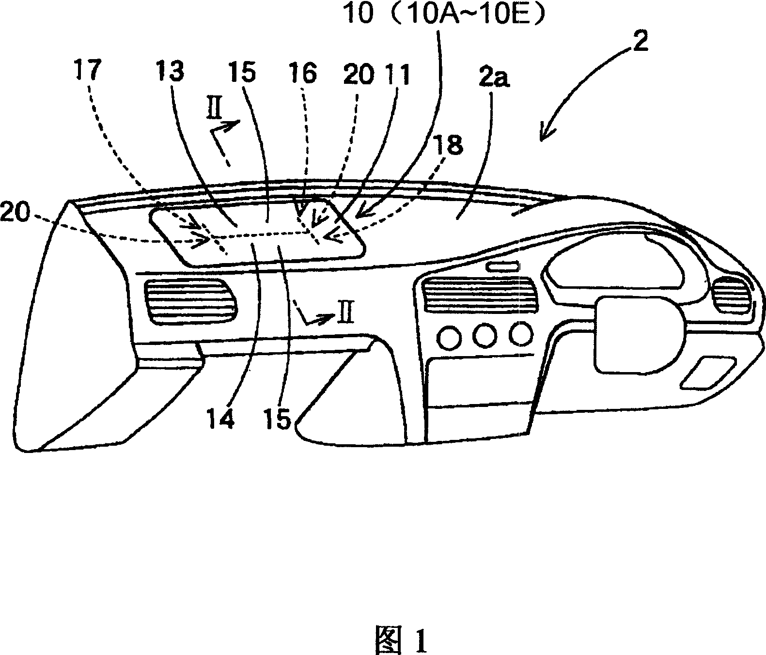
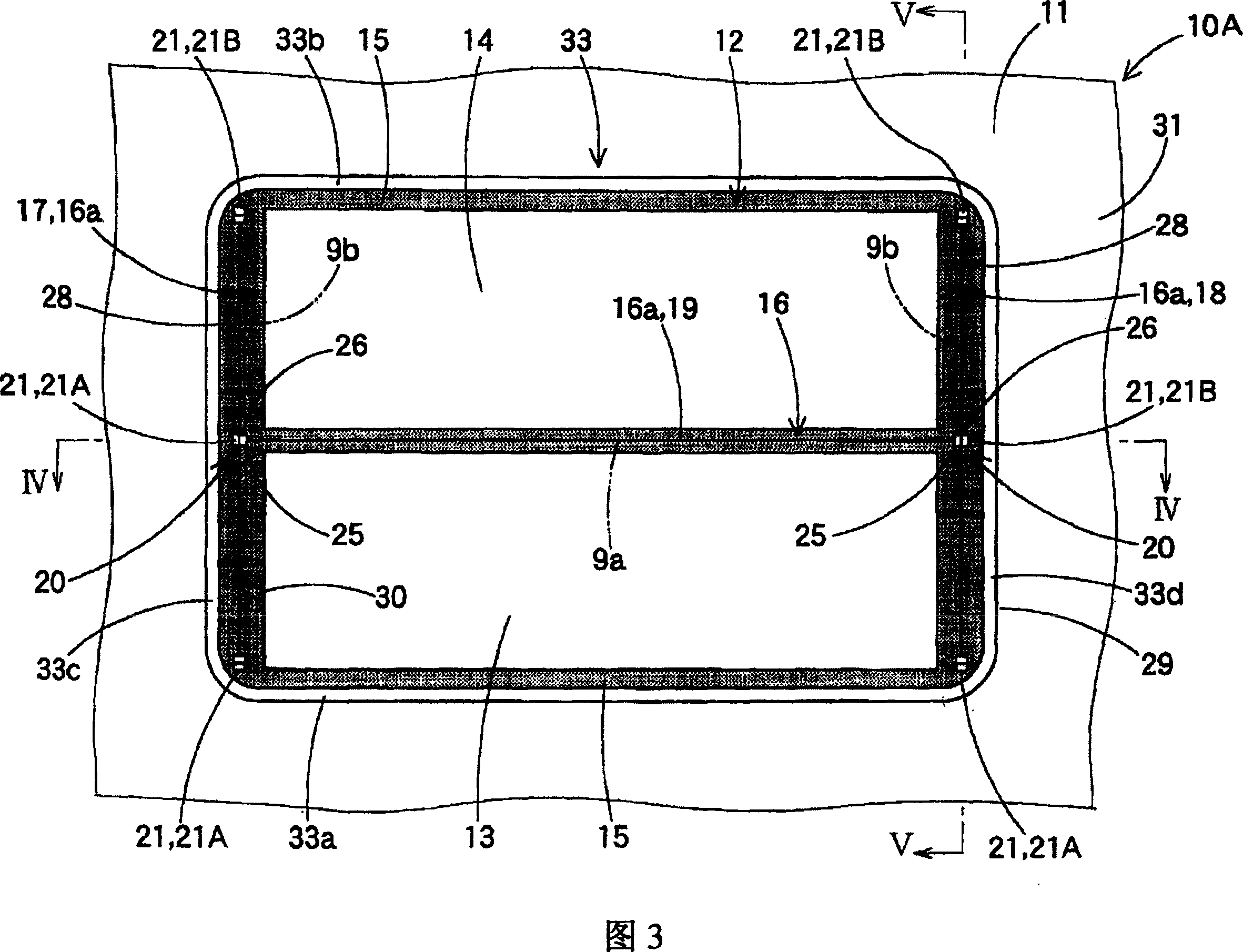
[0093] A first embodiment of the present invention will be described below. In the first embodiment, as shown in FIGS. 3 to 5 , the protrusion opening portion 12 is formed in a rectangular plate shape, and a thin prefabricated breaking portion 16 extending in a linear shape is provided thereon. This prefabricated breaking portion 16 is formed by providing a groove portion 16a which is recessed from the back surface side of the airbag cover 10A to the front surface side, and, in the case of the present embodiment, arranging T-shaped intersections at two places. The portion 20, viewed from the top, is such that the transverse portion 19 intersects the straight portions 17, 18 respectively in a T-shape, whereby the prefabricated rupture portion 16 is formed in an H-shape when viewed from the top. Thus, when the prefabricated breaking part 16 is broken, the two front and rear cover parts 13, 14 (the transverse part 19 is located therebetween) are respectively opened front and rear...
no. 2 approach
[0121] Next, a second embodiment of the present invention will be described with reference to FIGS. 14 to 20 .
[0122] In a second embodiment, as shown in FIG. 14 , the prefabricated break 16 consists of two different types of grooves 16a, 16b. The two straight break portions 17, 18 are formed by the groove 16b which is molded when the airbag cover 10B is injection-molded. The cross section 19 is constituted by the groove 16a, and the molded airbag cover 10B is machined using a cutter 35 to make a notch without generating chips or cutting material to form the groove 16a.
[0123] In the case of the second embodiment, as shown in FIGS. 16A to 16C , the cutter 35 is an ultrasonic cutter whose body portion 36 has a thickness of 0.5 mm to 1.0 mm and includes a single cutting edge 37 . The cutting edge 37 is formed obliquely in such a manner that the cutting edge 37 extends from the tip or tip 37a to the heel or near base 37b side thereof, in the direction in which the knife 35 m...
no. 3 approach
[0140] Although in the second embodiment, the cutting edge accommodating portion 21 is formed in a concave shape having a trapezoidal cross-section as viewed in the transverse direction of the transversal portion 19, the third embodiment shown in FIGS. 21 and 22 Like the airbag cover 10C of the embodiment, it is also possible to employ the cutting blade receiving portion 41 formed in a concave shape having a triangular cross section when viewed in the lateral direction of the transverse portion 19 . As in the case of the first embodiment, in the airbag cover 10C of the third embodiment, not only the transverse portion 19 but also the straight portions 17 , 18 are formed using the cutter 35 or by a cutting operation. That is, except for the cutting edge receiving portion 41, the prefabricated breaking portion 16 is constituted only by the groove 16a made by the cutting operation. In addition, cutting edge receiving portions 41 are provided at both ends of the respective straigh...
PUM
| Property | Measurement | Unit |
|---|---|---|
| thickness | aaaaa | aaaaa |
Abstract
Description
Claims
Application Information
 - R&D Engineer
- R&D Manager
- IP Professional
- Industry Leading Data Capabilities
- Powerful AI technology
- Patent DNA Extraction
Browse by: Latest US Patents, China's latest patents, Technical Efficacy Thesaurus, Application Domain, Technology Topic, Popular Technical Reports.
© 2024 PatSnap. All rights reserved.Legal|Privacy policy|Modern Slavery Act Transparency Statement|Sitemap|About US| Contact US: help@patsnap.com


