Device for ventilation

A technology of ventilation ducts and passages, which is applied in the field of indoor ventilation devices and can solve problems such as pressure differences

Inactive Publication Date: 2007-07-18
孔斯贝格汽车公司
View PDF0 Cites 0 Cited by
  • Summary
  • Abstract
  • Description
  • Claims
  • Application Information

AI Technical Summary

Problems solved by technology

This known valve or lance arrangement further tends to cause pressure differentials

Method used


Image

  • Device for ventilation
  • Device for ventilation

Examples


Embodiment Construction

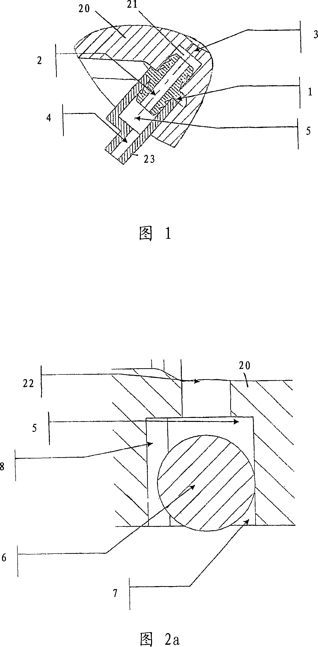
[0022] Figure 1 illustrates a nozzle arrangement according to the prior art. It can be seen from FIG. 1 that the outlet nozzle 1 is fixed in a recess 21 provided on the chamber wall 20 . A conduit 3 is arranged to communicate between this chamber and the recess 21 . The discharge nozzle 1 is provided with a through ventilation duct 2 . A discharge nozzle liner 23 connected to the discharge nozzle 1 is provided with a collection chamber 5 and a conduit 4 to the atmosphere. Through this nozzle arrangement a channel is thus established between the chamber and the outside of the chamber for the removal of air from the chamber. As can be seen in FIG. 1 , the chamber is protected by a duct 4 to the atmosphere against the displacement of contaminants such as eg splashed water relative to the ventilation duct 2 . Water splashed into the atmosphere duct 4 from the outside must pass through a circuitous path between the duct 4 leading to the atmosphere and the ventilation duct 2 to r...


PUM


Abstract

A device for ventilation of a chamber comprising a through-going passage constructed in the chamber wall and providing communication between the interior and the exterior of the chamber. The passage comprises a ventilation duct (22) extending from the interior of the chamber and communicating with a discharge duct (8) leading to the outside of the chamber. The ventilation duct (22) has an opening to a cavity (7) provided in the chamber wall, where the cavity (7) has an opening to the outside of the chamber. The device is further characterised in that a blocking body (6) is mounted in the cavity (7), the blocking body (6) being secured in the cavity (7) by a portion of the blocking body (6) being received in a holding opening provided in connection with the cavity (7). The discharge duct (8) is positioned in the wall of the chamber in such a manner that when the device's components are brought into operational position, the outlet of the discharge duct (8) is positioned lower than the cavity's opening to the outside of the chamber.

Description

technical field [0001] The invention relates to a device for room ventilation according to the independent claim. Background technique [0002] In hydraulic or pneumatic systems employing one or more cylinders, no components or parts of a single cylinder are under pressure during operation, nor are those same components or parts located directly in open air. If the non-pressurized part is a closed chamber, a vent path to the atmosphere must be provided to prevent the chamber from being pressurized by movement of parts passing through the chamber, such as movement of a cylinder piston. Additionally, ventilation paths must be provided in such a way that contaminants are prevented from entering the chamber. [0003] The device according to the invention will preferably be used for chamber ventilation such as the chambers described herein, but it will be appreciated by those skilled in the art that it may also be employed with other types of chambers or compartments requiring v...

Claims


Application Information

Patent Timeline
Patent Type & Authority Applications(China)
IPC IPC(8): F16K24/06F16K24/04F16K
CPCF16K24/06F16K24/04F15B21/044F16K24/046F16K31/32
Inventor 莫妮卡·H·汉森亚历山大·克里斯托弗森
Owner 孔斯贝格汽车公司
Why Eureka
Try Eureka