Antenna substrate of high dielectric coefficient and its antenna

A technology with high dielectric coefficient and dielectric coefficient, applied in antennas, antenna parts, circuits, etc., can solve the problems of increased assembly cost and material cost, increased cost of scattered capacitors, limited capacitive coupling, etc., to reduce microwave radiation. The effect of wavelength, material cost saving, assembly cost reduction

Inactive Publication Date: 2007-07-18
IND TECH RES INST
View PDF2 Cites 9 Cited by
  • Summary
  • Abstract
  • Description
  • Claims
  • Application Information

AI Technical Summary

Problems solved by technology

However, the setting of scattered capacitors will increase the cost, and the coils of the general substrate have limited capacitive coupling
[0006] The antenna structure disclosed in U.S. Patent No. 6,885,341 uses ferromagnetic materials to increase antenna efficiency, plus scattered surface mount components for circuit matching, but its ferromagnetic embedding will increase production costs
[0007] In the traditional antenna design, because the capacitor is placed externally, it will inevitably increase the assembly cost and material cost

Method used


Image

  • Antenna substrate of high dielectric coefficient and its antenna
  • Antenna substrate of high dielectric coefficient and its antenna
  • Antenna substrate of high dielectric coefficient and its antenna

Examples


Embodiment Construction

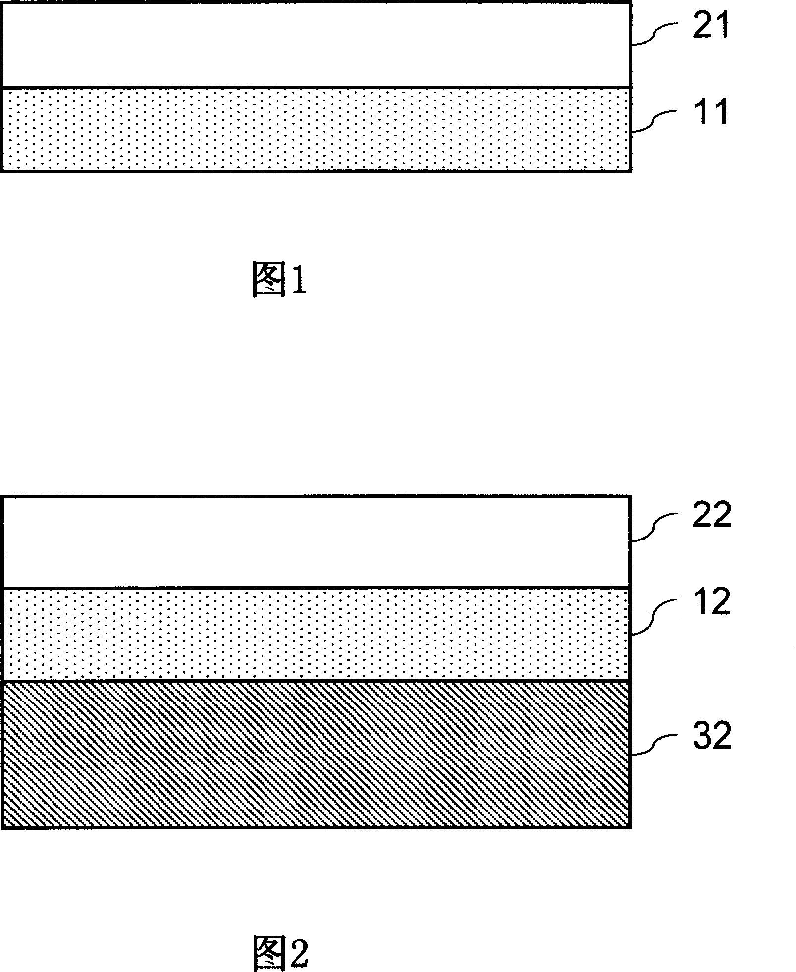
[0057] FIG. 1 is a schematic structural diagram of the first embodiment of the high dielectric constant antenna substrate disclosed in the present invention. As shown in the figure, the antenna substrate is composed of a first dielectric layer 11 and a second dielectric layer 21 to form a composite substrate. The first dielectric layer 11 is a high dielectric constant material with a first dielectric constant. The second dielectric layer 21, formed on one side of the first dielectric layer 11, has a second dielectric coefficient, wherein the second dielectric coefficient of the second dielectric layer 21 is lower than the first dielectric coefficient of the first dielectric layer 11 A dielectric coefficient.

[0058] Please refer to FIG. 2 , which is a schematic structural diagram of a second embodiment of the high dielectric constant antenna substrate disclosed in the present invention. As shown in the figure, the antenna substrate is composed of a first dielectric layer 12 a...


PUM


Abstract

The invention discloses an antenna substrate with high dielectric coefficient, including a first and a second dielectric layer. The first dielectric layer has a first dielectric coefficient, the second layer forms on one side of the first layer with a second dielectric coefficient, and the second dielectric coefficient is lower than the first one. In addition, the optional first and second metal layer form on the same side or both sides of the first dielectric layer to form a capacitor.

Description

technical field [0001] The invention relates to an organic substrate antenna, in particular to an organic substrate antenna with high dielectric coefficient. Background technique [0002] Wireless communication technology is accomplished through the radiation of electromagnetic waves. The generation of electromagnetic waves is basically the process of changing the electric field and magnetic field, and the energy is transmitted in the form of waves in space. The existence of the antenna provides an environment for electric field changes, and its geometric shape determines the space where the electric field may oscillate. Generally speaking, the materials that can produce antenna effects are mostly metal. [0003] Due to the rapid development of wireless communication technology and semiconductor manufacturing in recent years, wireless communication has become a necessity of life. At the same time, it has created a vigorous development of the global communication market. T...

Claims


Application Information

Patent Timeline
Patent Type & Authority Applications(China)
IPC IPC(8): H01Q1/00H01Q1/38
Inventor 卓威明陈昌升
Owner IND TECH RES INST
Why Eureka
Try Eureka