


Quick Research
Generate reliable direction feasibility study reports for your R&D in just a few steps.

Technical Q&A
Discover and master advanced knowledge NOW. Basics, ideas, possibilities, all at once.

Find Solutions
As an expert in R&D theories, this can generate solutions to your technical problems instantly.

Evaluate Feasibility
Analyze your overall solution with one click, know your potential R&D risks in advance.

Monitor Landscape
Get weekly tech updates, stay abreast of the latest tech innovations and key insights.
LED module
A technology of light-emitting diodes and modules, applied in the direction of electrical components, electric solid-state devices, circuits, etc., can solve the problem of reducing the space of light-emitting diode modules, achieve the best combination shape adaptability, make full use of the space structure, and the effect of thin volume
- Summary
- Abstract
- Description
- Claims
- Application Information
AI Technical Summary
Problems solved by technology
Method used
Image

Examples
Embodiment Construction
[0040] In order to further explain the technical means and effects of the present invention to achieve the intended purpose of the invention, the specific implementation, structure, characteristics and effects of the light-emitting diode module proposed according to the present invention will be described below in conjunction with the accompanying drawings and preferred embodiments. , as detailed below.
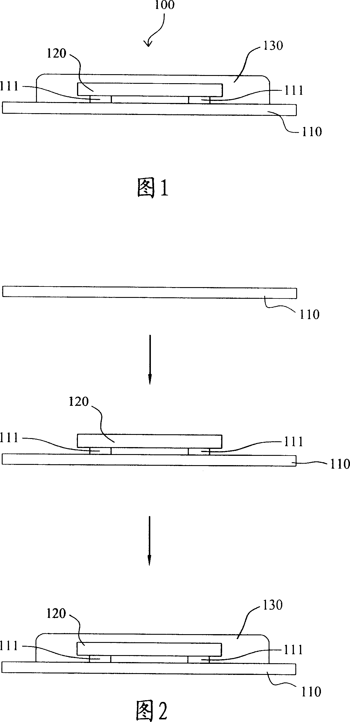
[0041] Please refer to FIG. 1 , which shows a schematic cross-sectional view of a light emitting diode module according to a preferred embodiment of the present invention. The LED module 100 includes a substrate 110 , a LED 120 and an encapsulation layer 130 .
[0042]The substrate 110 is the base of the LED module 100 for carrying other components. The material of the substrate 110 has insulating properties, so a circuit can be fabricated on the substrate 110, and the circuit includes a eutectic metal 111, which can be used to electrically connect with other components in a...
PUM
| Property | Measurement | Unit |
|---|---|---|
| Total thickness | aaaaa | aaaaa |
| Thickness | aaaaa | aaaaa |
Abstract
Description
Claims
Application Information
 - R&D Engineer
- R&D Manager
- IP Professional
- Industry Leading Data Capabilities
- Powerful AI technology
- Patent DNA Extraction
Browse by: Latest US Patents, China's latest patents, Technical Efficacy Thesaurus, Application Domain, Technology Topic, Popular Technical Reports.
© 2024 PatSnap. All rights reserved.Legal|Privacy policy|Modern Slavery Act Transparency Statement|Sitemap|About US| Contact US: help@patsnap.com