Machine tool for synchronously cutting and processing workpiece with multiple-groove on surface
A technology of synchronous cutting and processing machine tools, which is applied in the direction of electric processing equipment, metal processing equipment, manufacturing tools, etc., can solve the problems of inconvenience, low efficiency, and difficulty in meeting production requirements, and achieve simple structure, improved processing efficiency, and design ingenious effect
- Summary
- Abstract
- Description
- Claims
- Application Information
AI Technical Summary
Problems solved by technology
Method used
Image

Examples
Embodiment 1
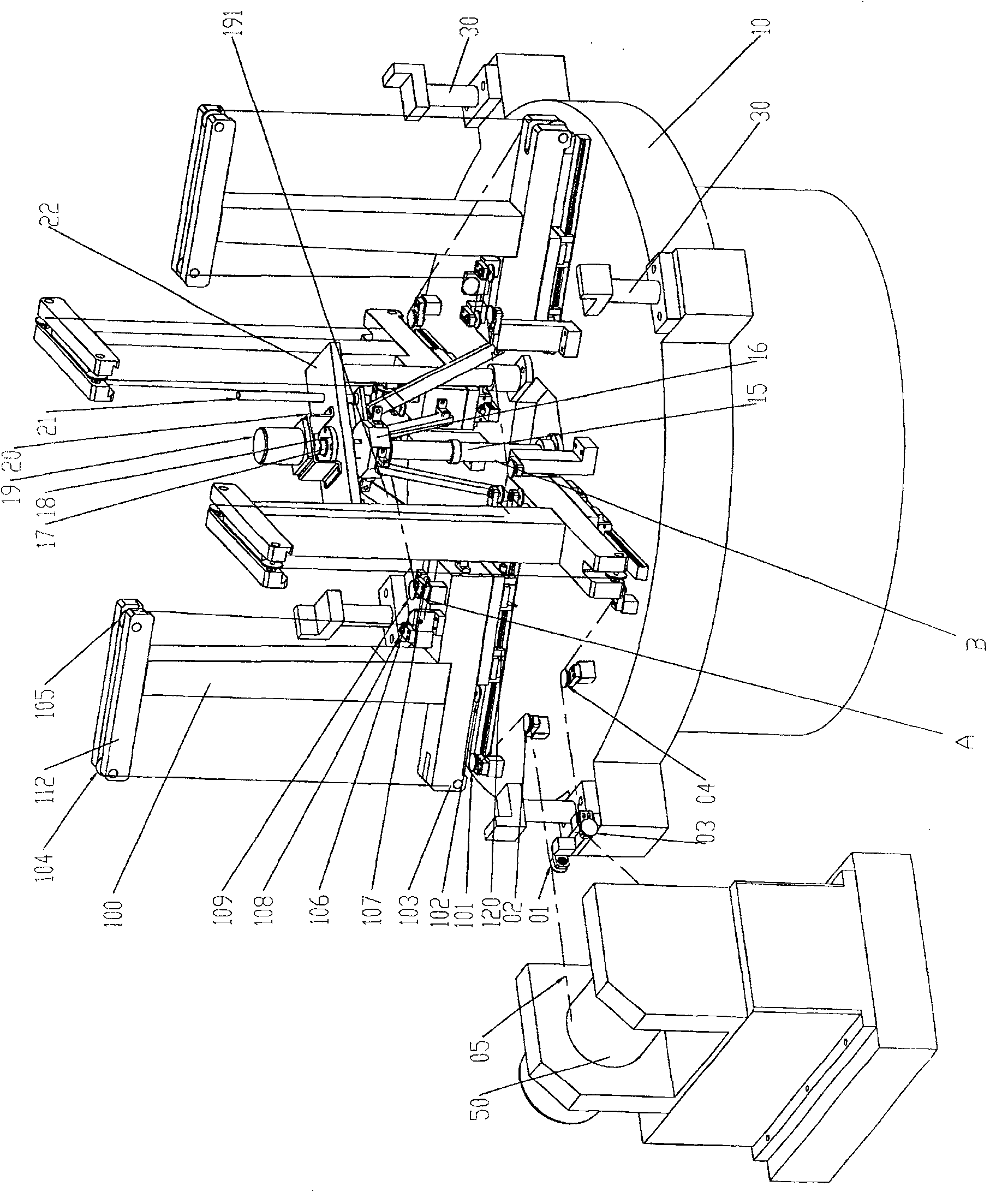
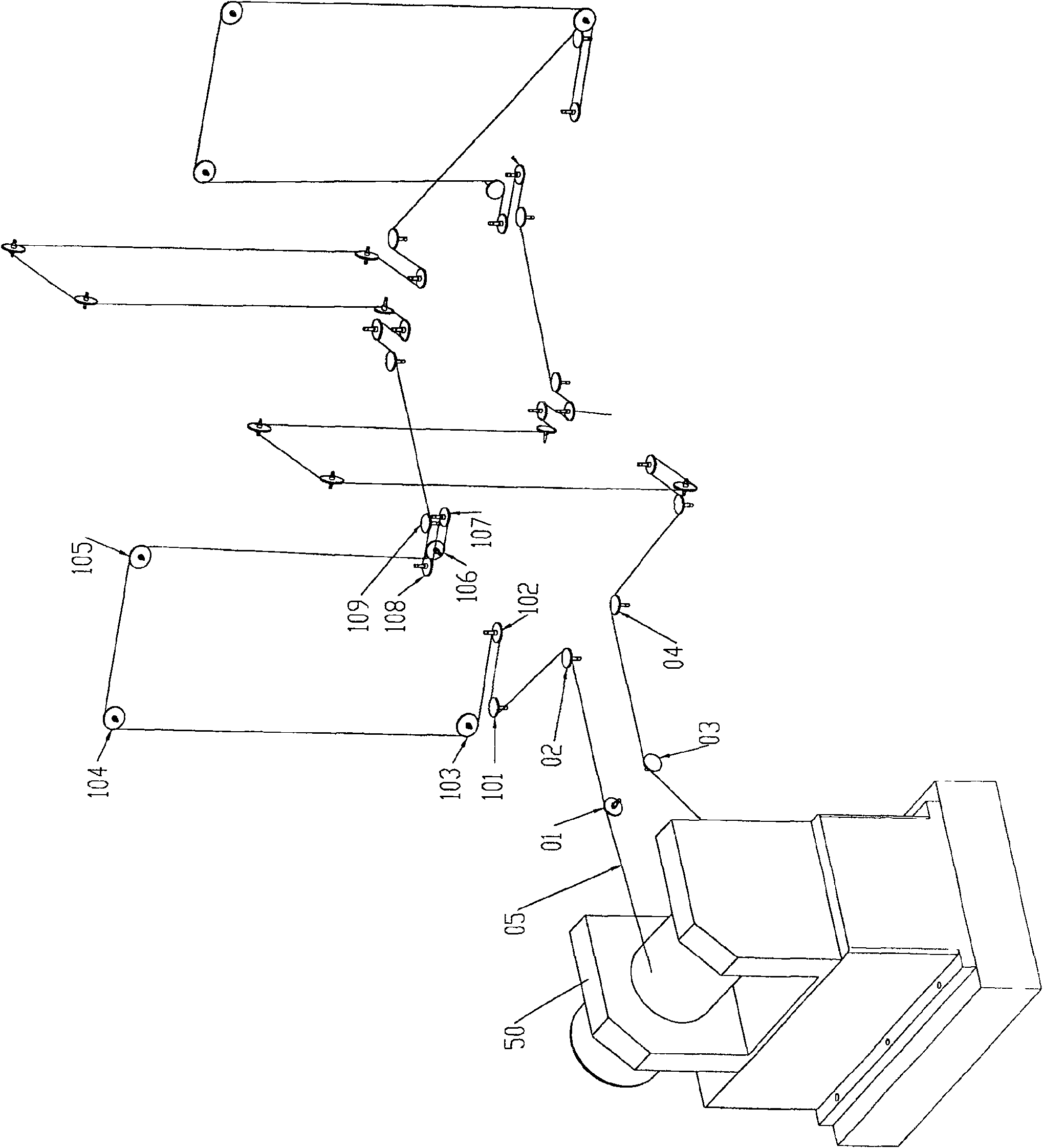
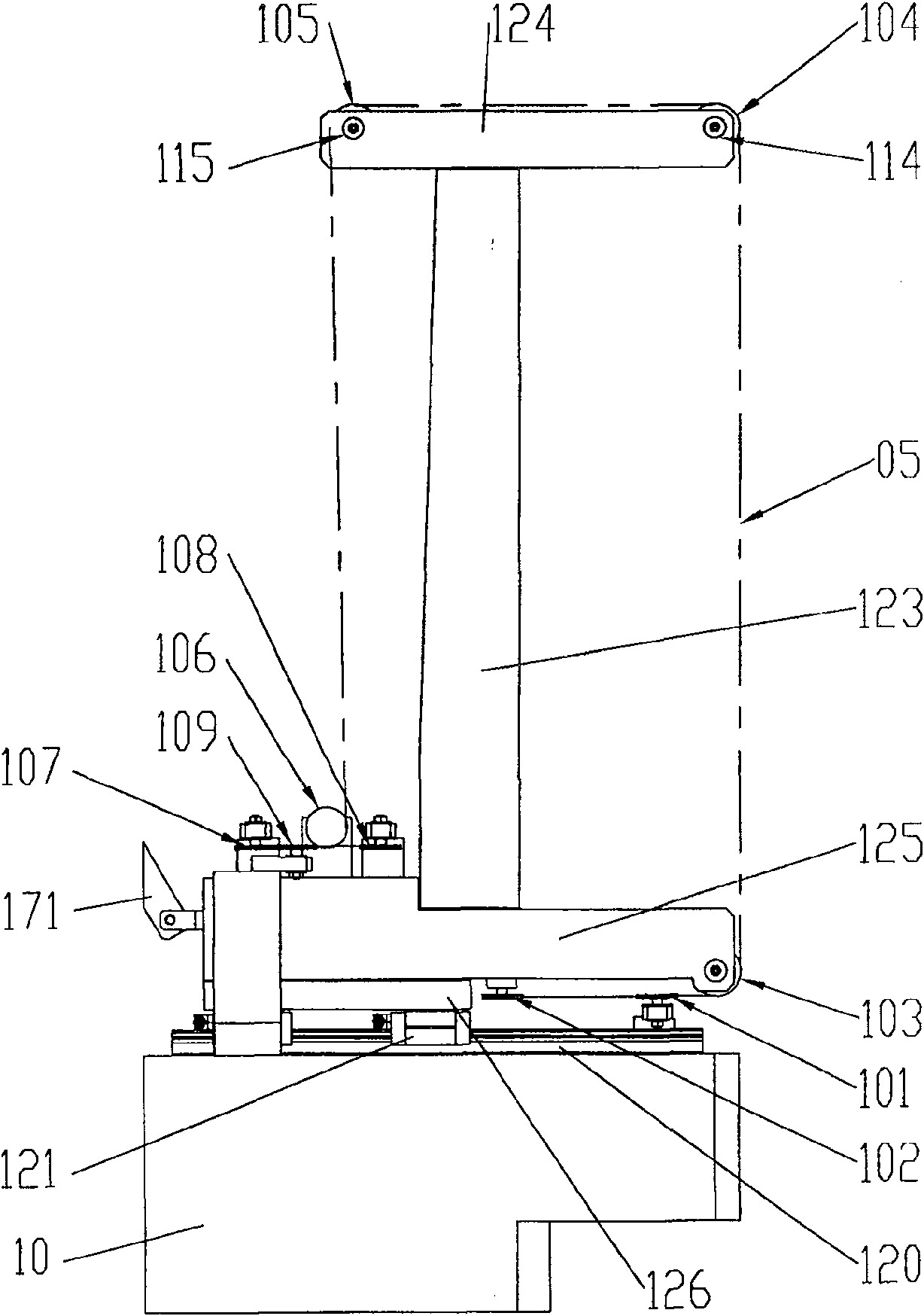
[0029] The structure diagram of the present invention is as figure 1 , 2 , 5, including a workbench 10 for installing workpieces, a thread rolling drum 50 for installing wire 05 for wire cutting, wherein the circumferential direction of the workbench 10 is equipped with several grooving wire racks 100, and several grooving wire racks 100 are all fixed on the workbench 10 through the corresponding guide rail moving pair 120 arranged in the radial direction of the workbench 10, and each grooving wire rack 100 is equipped with a guide wheel set consisting of several guide wheels required for processing. A. The wire 05 installed on the thread rolling cylinder 50 is wound into several guide wheels installed on the first grooving wire frame 100 through the wire feeding guide wheel 01, and then wound on the adjacent grooving wire frame 100 to install Several guide wheels, bypass the several guide wheels installed on the last grooving wire frame 100, and then return to the thread rol...
Embodiment 2
[0035] The structure of this embodiment is the same as that of Embodiment 1, the difference is that the driving device B is different from that of Embodiment 1, and the structural diagram of the driving device B of this embodiment is as follows Figure 7 As shown, it includes a second driving disc 80 driven by a motor to rotate. The geometric center of the second driving disc 80 coincides with the geometric center of the workpiece. Each grooving wire rack 100 is correspondingly fixed with a connecting rod 181 , one end 182 of the connecting rod 181 is hinged to the grooving wire frame 100 , and the other end 180 is hinged to the second driving disc 80 .
[0036] When the present invention works, when the motor drives the drive plate 70 to move, the connecting rod drives the grooving wire frame 100 to feed or retreat relative to the workpiece along the guide rail, so as to realize the grooving process of the workpiece by the silk thread.
Embodiment 3
[0038] The structure of this embodiment is the same as that of Embodiment 1, the difference is that the driving device B is different from that of Embodiment 1, and the structural diagram of the driving device B of this embodiment is as follows Figure 8 As shown, it includes a screw rod 15 driven by a stepping or servo motor 19 to rotate and a drive nut 16 forming a screw drive pair with it. The geometric center of the screw rod 15 coincides with the geometric center of the workpiece. Each grooving wire rack 100 are correspondingly fixed with a connecting rod 23, one end of the connecting rod 23 is hinged with the grooving wire frame 100, and the other end is hinged with the drive nut 16.
[0039] Above-mentioned drive nut 16 is installed on the fixed plate 22 that is limited by anti-rotation guide column 21 and it can not rotate, stepper or servomotor 19 is fixed on the fixed plate 22 by motor support 20, the output shaft of stepper motor 19 passes through shaft coupling Dev...
PUM
 Abstract
Description
Claims
Application Information
 - Generate Ideas
- Intellectual Property
- Life Sciences
- Materials
- Tech Scout
- Unparalleled Data Quality
- Higher Quality Content
- 60% Fewer Hallucinations
Browse by: Latest US Patents, China's latest patents, Technical Efficacy Thesaurus, Application Domain, Technology Topic, Popular Technical Reports.
© 2025 PatSnap. All rights reserved.Legal|Privacy policy|Modern Slavery Act Transparency Statement|Sitemap|About US| Contact US: help@patsnap.com