Electric connector with locking ring

An electrical connector, locking ring technology, applied in the direction of connection, two-pole connection, hose connection device, etc., can solve problems such as high production costs

Inactive Publication Date: 2010-02-17
TYCO ELECTRONICS BELGIUM EC
View PDF3 Cites 1 Cited by
  • Summary
  • Abstract
  • Description
  • Claims
  • Application Information

AI Technical Summary

Problems solved by technology

This leads to high production costs

Method used


Image

  • Electric connector with locking ring
  • Electric connector with locking ring
  • Electric connector with locking ring

Examples


Embodiment Construction

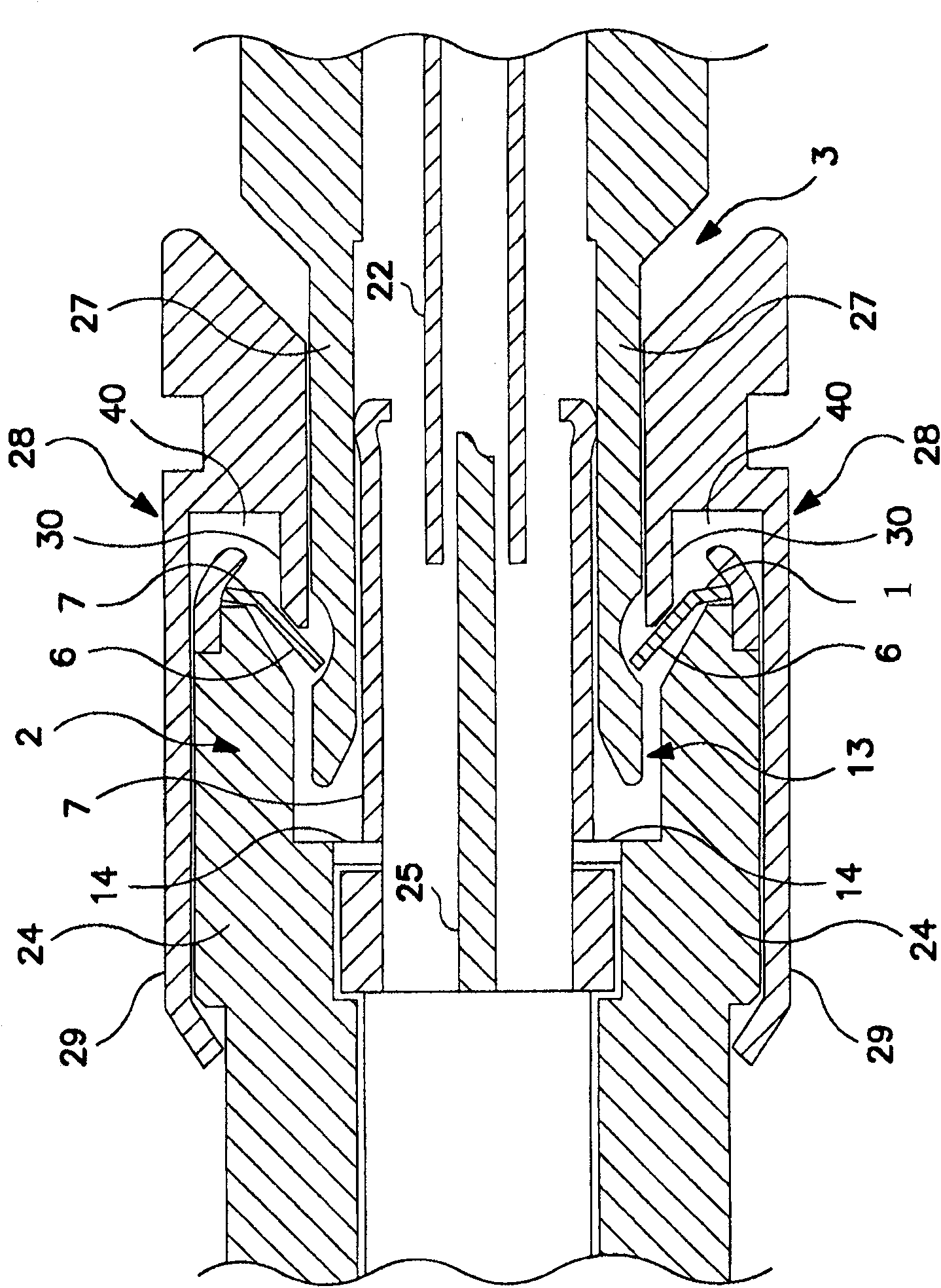
[0020] figure 1 A connector system with a first connection part 2 , a second connection part 3 and a locking ring 1 is shown. like figure 1 and 2 As shown, the first connecting part 2 has a bushing body 24 . The bushing body 24 has an opening 13 in which the first bushing 7 is arranged. This first bush 7 has an annular cross section. The contact pin 25 is arranged in the center of the first bush 7 . The first bush 7 and the contact pin 25 are electrically insulated and they can be used to conduct different potentials. For example, the first bushing 7 can serve as a signal shield for the contact pin 25 . The bush body 24 comprises a stop bush made of metal and having a curved edge 12 at its front end. This curved edge 12 is curved inwardly in the direction of the first bushing 7 . The locking ring 1 is arranged between the front end of the bushing body 24 and the bent edge 12 . The distance between the front end of the bushing body 24 and the edge 12 may be greater tha...


PUM


Abstract

An electrical connector has a first connector member, a second connector member, and a locking ring. The first connector member has a first contact and an abutment surface. The second connector memberhas a second contact for electrical connection with the first contact and a groove. The locking ring is disposed on the first connector member and has latching fingers. The latching fingers are of atleast a first type and a second type. The first type has a different length than the second type so that the first type engages the groove when the abutment surface is a first distance from the groove and the second type engages the groove when the abutment surface is a second distance from the groove when the first and second connector members are mated to lock the first connector member to thesecond connector member.

Description

technical field [0001] The present invention relates to an electrical connector with a first connecting part, wherein the first connecting part and the second connecting part cooperate and are fixed to the second connecting part by means of a locking ring. Background technique [0002] An axially mating electrical connector includes a first connector that mates with a second connector. The first connecting piece has an axial hole and a first contact. The second connector has a second contact and a cylinder received in the axial bore. When the first connector and the second connector are mated, the first and second contacts are electrically connected. The cylindrical or axial bore includes a groove. A locking ring is arranged between the cylinder and the axial bore. The locking ring has latch fingers that cooperate with the grooves to prevent release of the first and second connectors. An example of such an axially mating electrical connector with a locking ring is discl...

Claims


Application Information

Patent Timeline
Patent Type & Authority Patents(China)
IPC IPC(8): H01R13/639H01R13/627F16L33/22F16L37/091
CPCF16L33/227H01R13/6277H01R2103/00H01R24/40F16L37/091F16L37/0915
Inventor 克里斯托弗·马修斯雷金纳德·利曼
Owner TYCO ELECTRONICS BELGIUM EC
Why Eureka
Try Eureka