
Subway tunnel air-bag type soft blowing pipe

A technology of tunnel air and air supply pipes, which is applied in the direction of hoses, pipes, and pipeline layouts. It can solve the problems of increasing the volume and weight of hoses, and the inconvenience of transporting and placing air supply pipes, so as to maintain smooth air volume and low cost. , making easy effects

Inactive Publication Date: 2010-02-17
深圳市华丽雅卫浴科技有限公司
View PDF3 Cites 0 Cited by
  • Summary
  • Abstract
  • Description
  • Claims
  • Application Information

AI Technical Summary

Problems solved by technology

In foreign countries, there are soft air supply pipes specially equipped for temporary air supply in case of fire or poisonous gas in the subway, but there are many hard circles in the pipe with the same diameter as the pipe, which is to prevent the air pipe from collapsing when blowing air. These hard rings increase the volume and weight of the hose, making it inconvenient to carry and place the air supply pipe

Method used

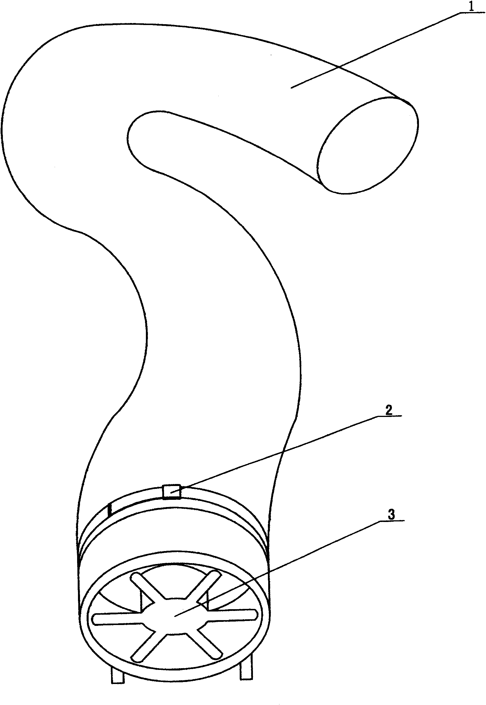
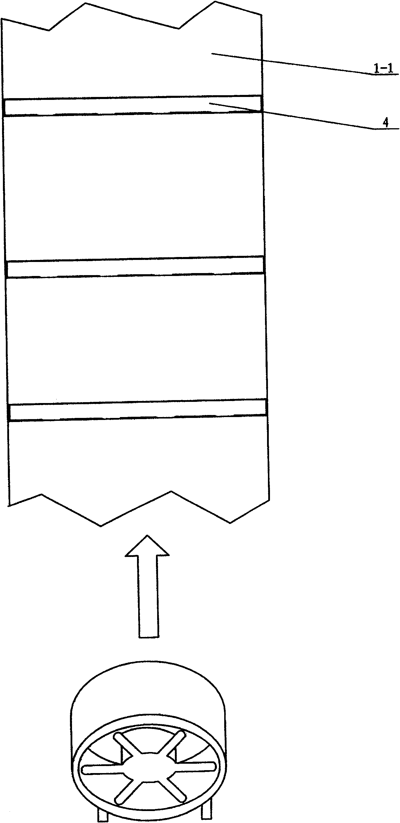
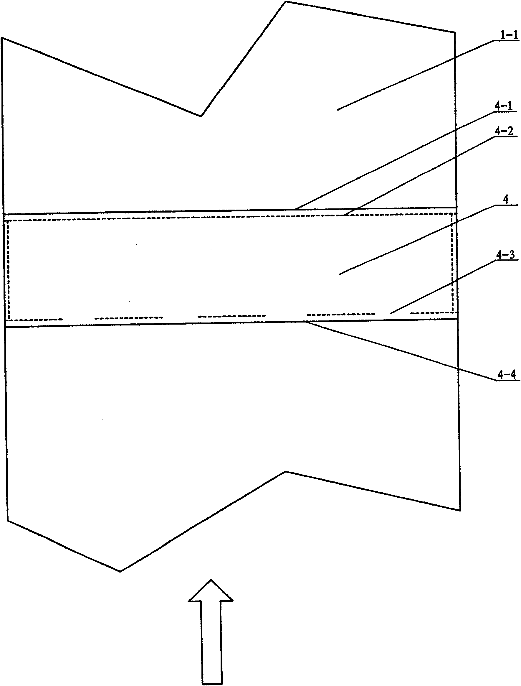

Image

  • Subway tunnel air-bag type soft blowing pipe
  • Subway tunnel air-bag type soft blowing pipe
  • Subway tunnel air-bag type soft blowing pipe

Examples


Embodiment approach 1

[0021] Embodiment 1 from figure 1 , figure 2 and image 3 Find out in, the software air supply pipe that the present invention introduces, the air supply pipe is made up of air pipe 1, air pipe tight buckle 2, air blower 3, wind pocket 4. On the air duct inner wall 1-1, a circle of wind pockets 4 is sewn at regular intervals (about 1.5 meters). The material used in the wind pockets 4 is the same as that of the air duct 1. Made of air-permeable fabric, the wind pocket cloth is cut into a long strip, and is directly sewn on the inner wall of the air duct 1-1 horizontally. When the wind pocket 4 is sewn, several wind pockets 4-3 are left, and the wind pocket is 4 points in front of the wind pocket. 4-4 and the wind pocket rear 4-1, the suture 4-2 near the wind pocket rear 4-1 is a whole seam, airtight; and the suture 4-2 near the wind pocket front 4-4 is left Wind pocket 4-3 place is not stitched, and wind is caught after blowing into wind pocket 4-3 from wind pocket, so it i...

Embodiment approach 2

[0027] Embodiment 2 Figure 10 It is the wind pocket 4 of another sewing method, and the wind pocket 4 is divided into small pockets by dividing sutures 4-5. Each small pocket is not connected to each other. A circle of the inner wall is made into several small pockets, correspondingly all have the air-ride opening 4-3, and the wind pocket 4 is filled with wind to make the air pipe 1 bulge, and the air supply pipe will not collapse. This method is that the wind pocket is relatively strong and can withstand a lot of wind.

Embodiment approach 3

[0028] Embodiment 3 Figure 11 It is the wind pocket 4 of another sewing method. There are dividing sutures 4-5 to divide the wind pocket 4 into small pockets, but the dividing sutures 4-5 are not sewn to the end, so there are left holes on both sides of the bottom of each small pocket. In this way, each small pocket is connected, and each small pocket has a wind pocket 4-3. This way, the wind pocket 4 will bulge better, and the separation stitches 4-5 strengthen the wind pocket 4. Strength, can withstand a lot of wind.


PUM


Abstract

Circular hood type soft blast tube is composed of fan, soft blast tube and circular hood etc. In time of air blowing, circular hood is plumped up, and blast tube is supported circularly so as to be good for a expedite flue. The soft blast tube is prepared as following: a round of circular hoods are tailored on inner wall of the blast tube in every distance (about 1.5 M); material of circular hoodis same to material of the blast tube; being cutting up into a long strip, cloth of circular hood is tailored on inner wall of the blast tube in transverse direction directly; several holes of circular hood prepared when tailoring circular hood. Cloth of circular hood is in use for front circular hood and back circular hood. After being sewed, the back circular hood is closed, no air going through. It is not sewing on the said holes on front circular hood. Thus, entering through the holes, wind plumps up the soft blast tube.

Description

technical field [0001] The invention relates to an air supply pipe, in particular to a soft air supply pipe for temporary air supply in subways or tunnels. Background technique [0002] At present, most of the air supply pipes on the market are hard pipes, but if they need to be used temporarily in subways or tunnels, hard pipes are not suitable and the cost is relatively high. In foreign countries, there are soft air supply pipes specially equipped for temporary air supply in case of fire or poisonous gas in the subway, but there are many hard circles in the pipe with the same diameter as the pipe, which is to prevent the air pipe from collapsing when blowing air. These hard rings increase the volume and weight of the hose, making it inconvenient to carry and place the air supply pipe. Contents of the invention [0003] According to the shortcomings of the above-mentioned inflatable cushions, the present invention has invented a soft air supply pipe with a wind pocket, w...

Claims


Application Information

Patent Timeline
Patent Type & Authority Patents(China)
IPC IPC(8): F24F13/02F16L11/00
Inventor 段云平
Owner 深圳市华丽雅卫浴科技有限公司
Learn More