
LED backlight module and its temperature control method

A temperature control method and backlight module technology, applied in the direction of energy-saving control technology, light source, electric light source, etc., can solve the problems of current reduction, inability to apply LED backlight module, no instructions, etc., and achieve the effect of avoiding the decline of life

Active Publication Date: 2010-01-20
HISENSE VISUAL TECH CO LTD
View PDF8 Cites 0 Cited by
  • Summary
  • Abstract
  • Description
  • Claims
  • Application Information

AI Technical Summary

Problems solved by technology

Due to the high brightness requirements of the backlight module, the LED backlight module needs to use a large number of LED lamps, which leads to the problem of temperature rise of the LED backlight module
Chinese patent application CN200410002701.5 provides an adjusting device for reducing the temperature of the LED light source by adding a fan, but due to space and noise control limitations, this method cannot be applied to LED backlight modules
However, the patent application does not explain how to reduce the current of the LED wick, and the key issues such as how much the current is reduced
Because LED backlight modules are generally used in display devices, if the current of the LED tube is too low, the brightness of the LED backlight will be too low, which will affect the user's viewing. If the current of the LED tube is limited, the LED backlight module The influence of temperature control is limited, and it is possible that after reducing the current of the LED tube, the temperature of the LED backlight module will continue to rise

Method used


Image

  • LED backlight module and its temperature control method
  • LED backlight module and its temperature control method
  • LED backlight module and its temperature control method

Examples


Embodiment Construction

[0030] In order to enable those skilled in the art to better understand the solution of the present invention, and to make the above-mentioned purpose, features and advantages of the present invention more obvious and understandable, the present invention will be further described in detail below in conjunction with the accompanying drawings and specific embodiments.

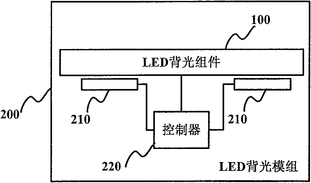
[0031] figure 1 Shown is a schematic diagram of a common LED backlight assembly. As shown in the figure, the LED backlight assembly 100 includes a reflective plate 110 , several LEDs 120 , a light guide plate 140 and a diffuser plate 150 . Wherein, the reflective plate 110 may be a circuit board with a reflective film on the surface; the LED 120 is fixed on the reflective plate 110 and connected to an external power source through a via hole on the reflective plate 110 . A light-conducting and heat-dissipating material is poured outside the LED 120 to form a light-conducting and heat-dissipating layer 130 . The...


PUM


Abstract

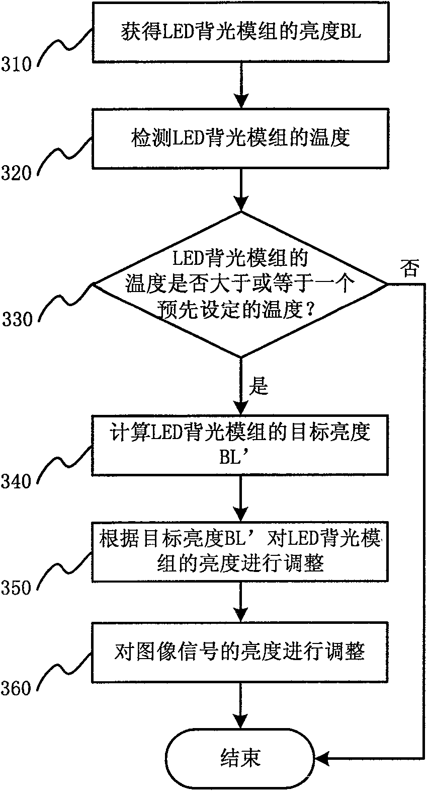
The invention provides an LED backlight module and a temperature control method thereof, and temperature of the LED backlight module is controlled within a safe range. Concretely, the temperature control method of the LED backlight module comprises: brightness BL of the LED backlight module is obtained; the temperature of the LED backlight module is measured; the temperature of the LED backlight module is compared with a preset temperature; if the temperature of the LED backlight module is more than or equal to the preset temperature, an objective brightness BL' of the LED backlight module is computed; and the brightness of the LED backlight module is adjusted according to the objective brightness BL'. The temperature control method of the LED backlight module detects the temperature of the LED backlight module, and when the temperature of the LED backlight module reaches or exceeds a critical temperature, the temperature control method plans to further raise the temperature of the LED backlight module by lowering the brightness of the LED backlight module, and consequently protects the LED backlight module and avoids the reduction of the service life of the LED backlight module.

Description

technical field [0001] The present invention relates to a temperature control method, in particular to a temperature control method of an LED backlight module. Background technique [0002] In recent years, the rapid development of the flat panel display (FPD) industry dominated by thin film transistor liquid crystal display technology (TFT-LCD) has brought unprecedented development opportunities to the upstream panel industry and optical material industry. Among them, the backlight is provided by CCFL, EEFL , LED, OLED, FFL and other light sources, the more mature one is CCFL. The full name of CCFL is Cold Cathode Fluorescent Lamp, that is, cold cathode lamp. CCFL seals an inert gas Ne+Ar mixed gas in a glass tube, which contains a small amount of mercury vapor (several mg), and coats phosphor on the inner wall of the glass. A high-voltage high-frequency electric field is applied between the two electrodes, and the mercury vapor is excited in this electric field to produce...

Claims


Application Information

Patent Timeline
Patent Type & Authority Patents(China)
IPC IPC(8): G09G3/34G09G3/36H05B37/02
CPCY02B20/42Y02B20/40
Inventor 刘卫东乔明胜陈兴锋黄国鹏
Owner HISENSE VISUAL TECH CO LTD
Learn More