
Determination method of horizontal hydraulic load at rotary wheel of water turbine-generator set

A technology of generator set and measurement method, which is applied in the field of rotor dynamics and experimental mechanics, and can solve problems such as inability to obtain phase, and failure to consider excitation mutual coupling

Inactive Publication Date: 2010-01-20
TSINGHUA UNIV
View PDF5 Cites 2 Cited by
  • Summary
  • Abstract
  • Description
  • Claims
  • Application Information

AI Technical Summary

Problems solved by technology

[0011] The purpose of the present invention is to provide a method based on experiments to measure the lateral hydraulic load at the runner of the hydroelectric generating set, aiming to solve the problems that the prior art cannot obtain the phase and does not consider the mutual coupling of various excitations, so as to obtain a direct A more realistic lateral hydraulic load expression for shafting response calculations

Method used


Image

  • Determination method of horizontal hydraulic load at rotary wheel of water turbine-generator set
  • Determination method of horizontal hydraulic load at rotary wheel of water turbine-generator set
  • Determination method of horizontal hydraulic load at rotary wheel of water turbine-generator set

Examples


Embodiment

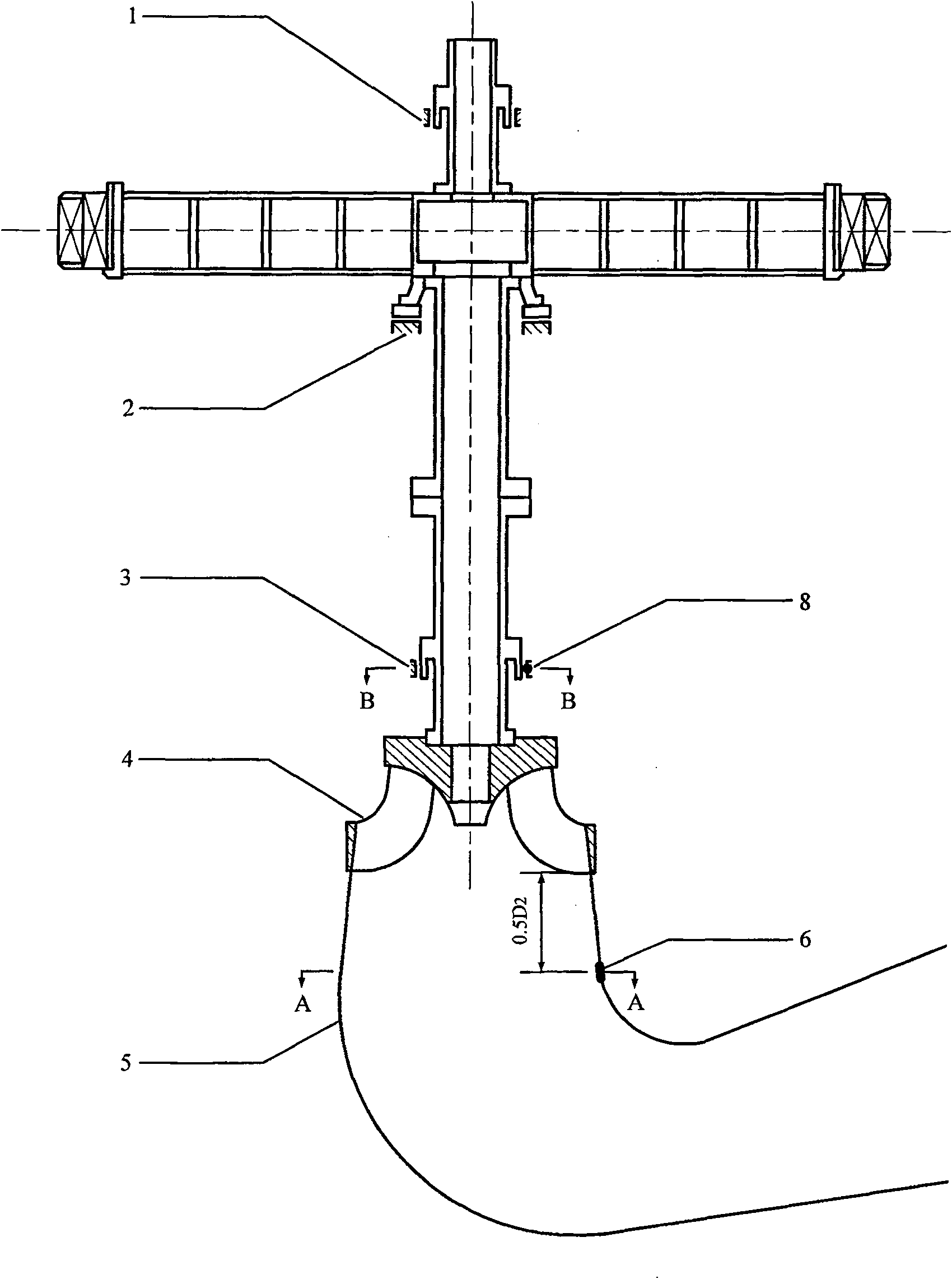
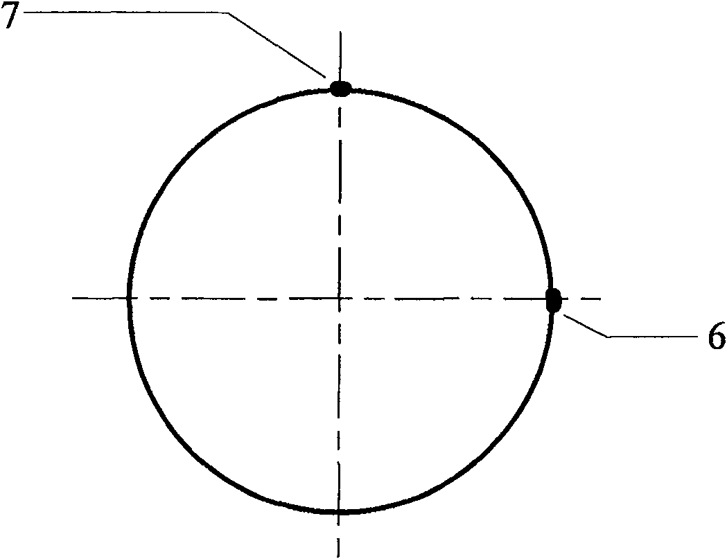
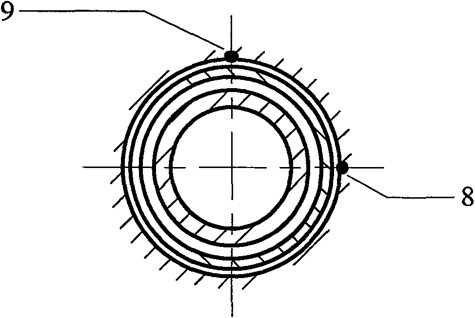
[0075] 1) figure 1 It is a schematic diagram of the Francis turbine shafting and the arrangement of measuring points. Since the experimental techniques involved are relatively mature, they will not be repeated here. In order to make the embodiment more concise, analog signals are used instead of measured signals. The difference is that the noise of the measured signal is filtered out before sampling ( Figure 4 ), while the analog signal can only be filtered after sampling, but this has no qualitative effect.

[0076] Analog signal:

[0077] (1) Pressure pulsation signal:

[0078] PI x =(10 4 +4×10 4 cos(7ωt+π / 2)+2×10 4 cos(14ωt+π)+500cos(9ωt+π / 3)+300cos(12ωt+π / 5)+gaussian white noise)Pa;

[0079] PI y =(10 4 +3×10 4 sin(7ωt+5π / 6)+1×10 4 sin(14ωt+5π / 6)+400sin(9ωt+2π / 3)+200sin(12ωt+3π / 5)+gaussian white noise)Pa;

[0080] (2) The displacement signal of the journal at the water guide bearing:

[0081] uI x =(0.5×10 -4 +0.5×10 -4 cos(ωt+π / 5)+2×10 -4 cos(7ωt+π / 5)+1...


PUM


Abstract

A method for measuring transverse hydraulic load at a runner of a hydro-generating unit relates to the method for determining the transverse hydraulic load at the runner by obtaining pressure pulsation in a tail pipe and displacement of a shaft neck at a water pilot bearing through experiments. The method comprises the following steps: a. a displacement signal of the shaft neck at the water pilot bearing, a pressure pulsation signal of the tail pipe and the frequency response feature of a shaft system of the hydro-generating unit are obtained through the experiments; b. amplitudes, frequencies and phases of main components of the pressure pulsation are obtained by analyzing the signal; c. the form of the transverse hydraulic load is assumed, and the frequency response feature is utilized to determine the flexibility coefficient of the shaft system under the action of the load; d. and the transverse hydraulic load is determined according to the maximum value of the displacement amplitude and the flexibility coefficient caused by the transverse hydraulic load. The method decomposes the transverse hydraulic load to the components with the different frequencies for superposition and measures the phase; furthermore, the pressure pulsation is the centralized reflection of the coupling action of various incentives in the tail pipe, and the obtained transverse hydraulic load is closer to the actual situation.

Description

technical field [0001] The invention relates to a method for measuring the lateral hydraulic load at the runner of a hydroelectric generating set, more specifically, to a method for determining the lateral hydraulic load at the runner by obtaining the pressure pulsation in the draft tube and the journal displacement at the water guide bearing through experiments. A load method, belonging to the field of rotordynamics and experimental mechanics. Background technique [0002] The main components of the hydroelectric generating set include the shaft, the generator rotor, the turbine runner, the guide bearing and the thrust bearing. Due to deviations in manufacturing and installation and different operating conditions, there are various unbalanced forces, mainly including three aspects: mechanical, electromagnetic and hydraulic. Under the action of these unbalanced forces, the hydroelectric generator set will vibrate. When the amplitude exceeds a certain range, friction between...

Claims


Application Information

Patent Timeline
Patent Type & Authority Patents(China)
IPC IPC(8): G01L5/00G01M10/00
Inventor 佀晓辉冯辅周褚福磊卢文秀赵景山
Owner TSINGHUA UNIV
Learn More