
Linear compressor

A linear compressor and pressurized fluid technology, applied to mechanical equipment, engine components, machines/engines, etc., can solve problems such as reduced efficiency

Active Publication Date: 2010-01-20
EMPRESA BRASILEIRA DE COMPRESSORES SA (EMBRACO)
View PDF9 Cites 2 Cited by
  • Summary
  • Abstract
  • Description
  • Claims
  • Application Information

AI Technical Summary

Problems solved by technology

[0003] However, when the compressor was actually used in a refrigeration unit, it demonstrated an unexpectedly rapid loss of efficiency

Method used


Image

  • Linear compressor
  • Linear compressor

Examples


Embodiment Construction

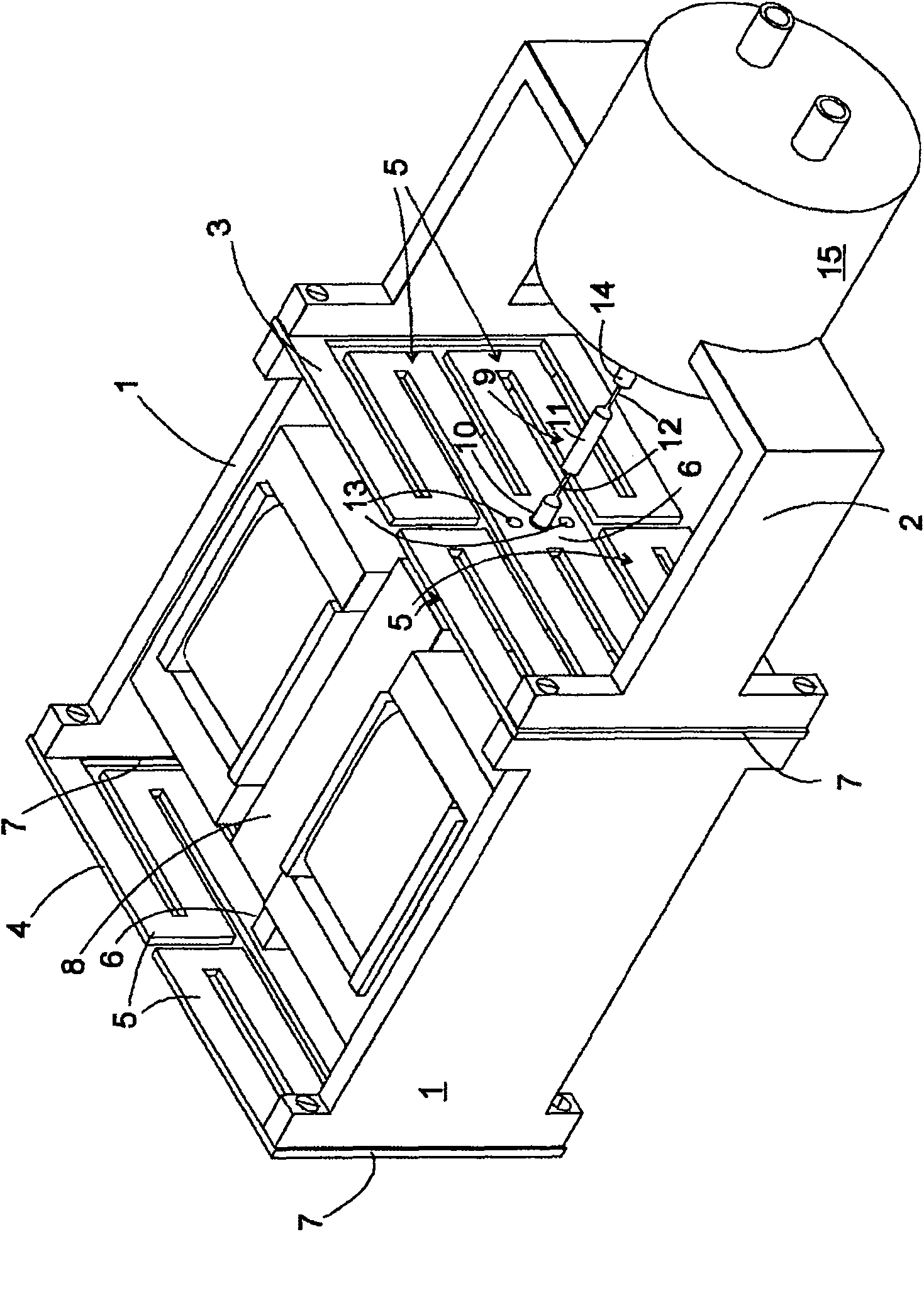
[0012] figure 1 The linear compressor shown in perspective view in , has a rigid, approximately U-shaped frame in plan view, which consists of three parts, namely two flat wall sections 1 and a bow 2 . A first diaphragm spring 3 is sandwiched between the end faces of the bow 2 facing each other and the two wall segments 1; On the end side facing away from the bracket.

[0013] The diaphragm springs 3 , 4 stamped from spring plates each have two elongated edge strips 7 and four spring arms 5 which overlap the end faces of the wall section 1 or bow 2 , the springs From the end of the edge strip 7 the arms extend in a zigzag pattern towards the middle section 6 at which the spring arms meet. The middle sections 6 each have three bores: two outer bores and a central bore, on which a permanently magnetic vibrating body 8 is suspended by means of screws or rivets 13 , for the diaphragm spring 3 an e.g. The rod section 10 , which is fastened to the vibrating body 8 by means of a s...


PUM


Abstract

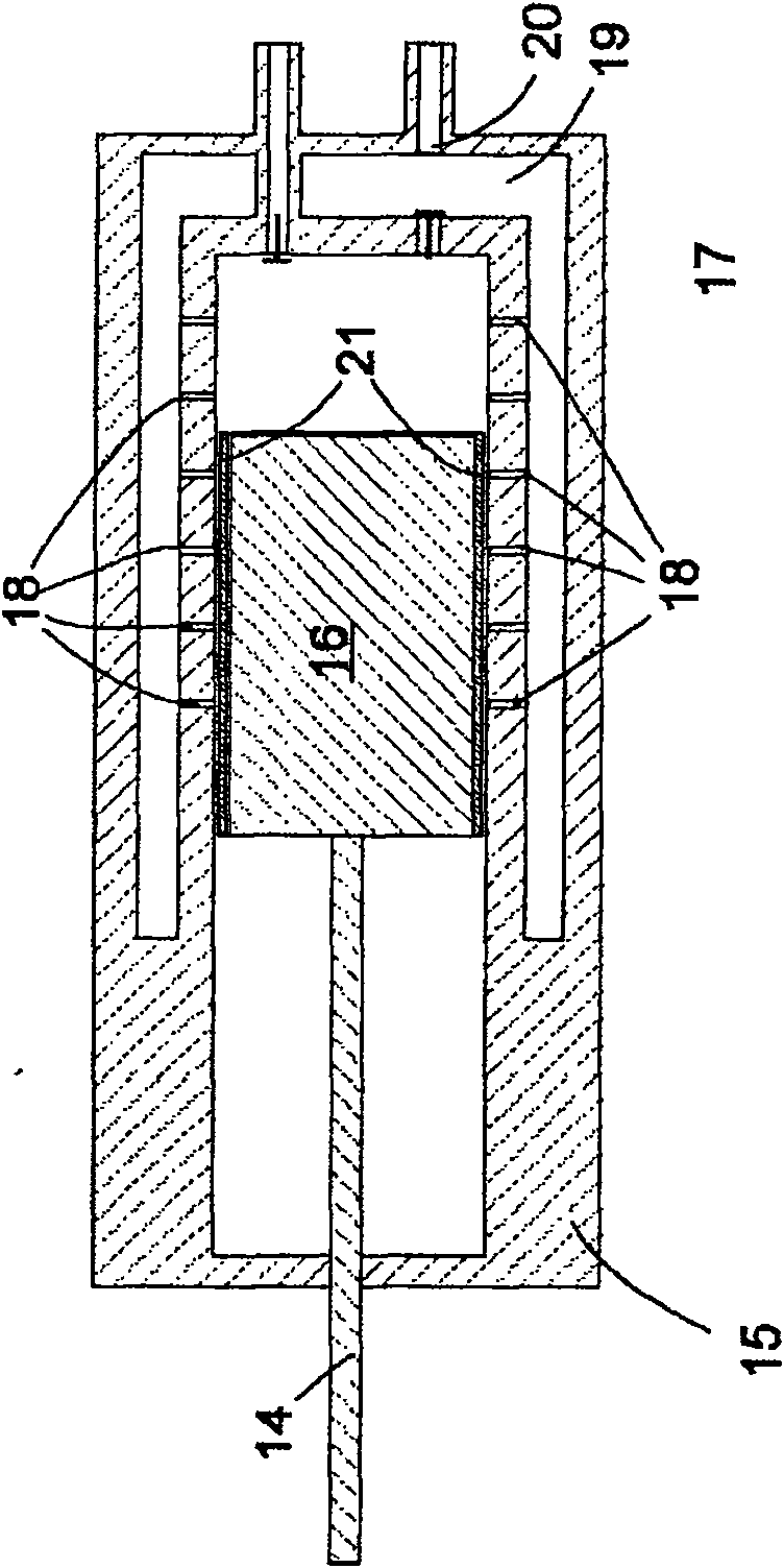
A linear compressor comprises a cylinder (15), a hydraulically borne piston (16) that can be longitudinally oscillated inside the cylinder (15) and a drive unit (1-14) driving the movement of the piston. The compressor is characterized in that at least one of the lateral faces of the piston (16) and the cylinder (15) that face each other is provided with an abrasion-resistant bearing coating (21).

Description

technical field [0001] The invention relates to a linear compressor, in particular for compressing refrigerant in refrigeration installations. Background technique [0002] A linear compressor according to the preamble of claim 1 is known from US 6 596 032 B2. In such a linear compressor, an annular hollow chamber is formed in the wall of the cylinder, which is supplied with pressurized fluid and communicates with the inner chamber of the cylinder via a plurality of openings distributed on the side wall of the cylinder, in which the piston Exercise indoors. The pressurized fluid entering the cylinder chamber through these openings forms a pad on which the piston slides without contact with the side walls. Since the pad avoids frictional contact between the piston and the cylinder, such linear compressors can operate for extended periods of time in continuous operation without significant loss of efficiency due to frictional wear. [0003] However, when the compressor is a...

Claims


Application Information

Patent Timeline
Patent Type & Authority Patents(China)
IPC IPC(8): F04B35/04
CPCF05C2253/12F05C2225/00F04B35/045
Inventor J-G·舒伯特G·斯洛塔
Owner EMPRESA BRASILEIRA DE COMPRESSORES SA (EMBRACO)
Learn More