
Synthetic aperture radar system using chaos signal

A synthetic aperture radar, chaotic signal technology, applied in radio wave measurement system, use re-radiation, radio wave reflection/re-radiation and other directions, can solve the difficulty of noise signal processing, the noise signal is not repeatable, and increase the complexity of the system degree and other issues to achieve the effect of improving the anti-interference performance

Active Publication Date: 2009-12-30
INST OF ELECTRONICS CHINESE ACAD OF SCI
View PDF9 Cites 0 Cited by
  • Summary
  • Abstract
  • Description
  • Claims
  • Application Information

AI Technical Summary

Problems solved by technology

[0004] The purpose of the present invention is to solve the problem that the noise signal does not have repeatability in the above-mentioned technology, and it is necessary to record the transmission waveform in real time or delay the transmission waveform, which increases the complexity of the system and the problem that the noise signal is difficult to process. In order to achieve the stated purpose, The invention provides a synthetic aperture radar system with high surveying and mapping bandwidth or resolution, easy to process noise signals, and using chaotic signals

Method used


Image

  • Synthetic aperture radar system using chaos signal
  • Synthetic aperture radar system using chaos signal
  • Synthetic aperture radar system using chaos signal

Examples


Embodiment Construction

[0023] The present invention will be described in detail below in conjunction with the accompanying drawings. It should be noted that the described embodiments are only intended to facilitate the understanding of the present invention, rather than limiting it in any way.

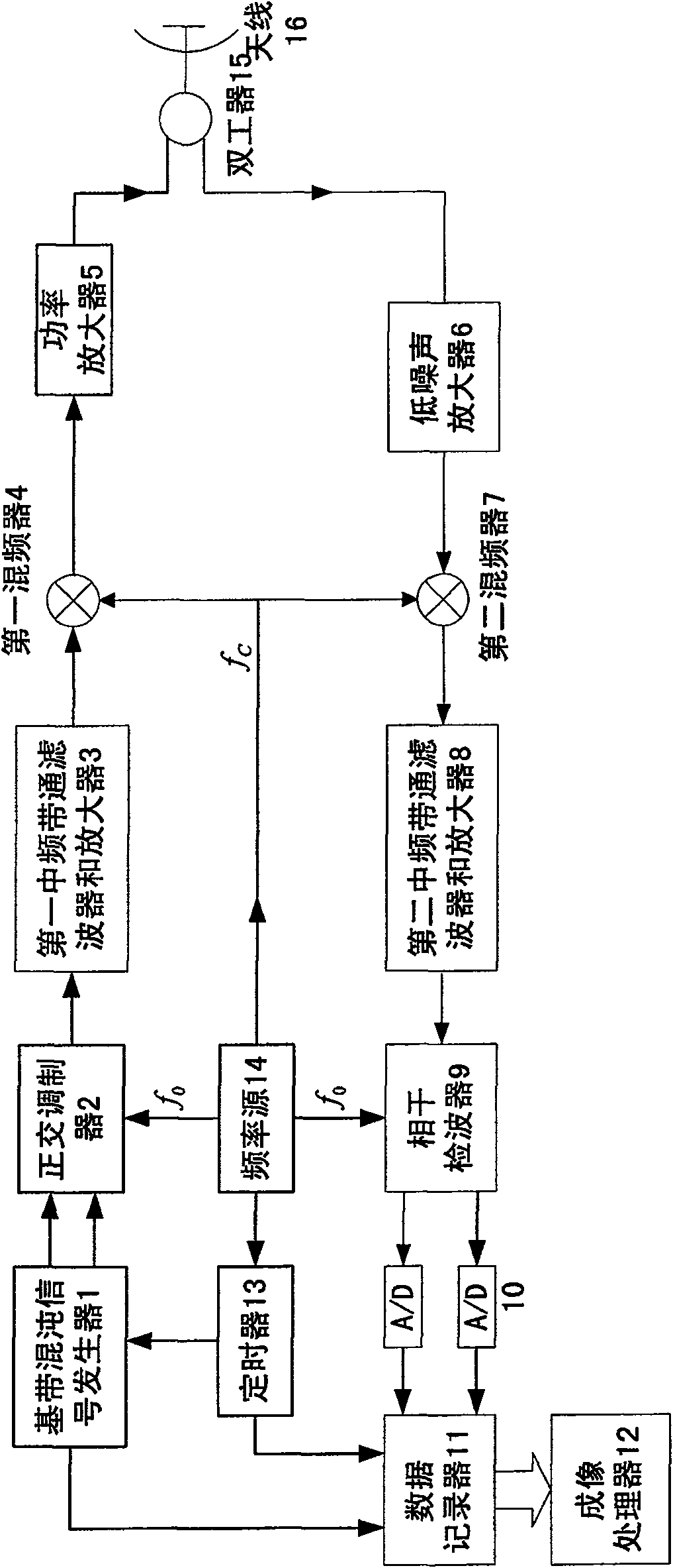
[0024] According to the present invention figure 1 , specifically, as shown in the structural block diagram of a synthetic aperture radar system using chaotic signals, in the present invention:

[0025] 1) According to the selected chaotic map and parameters, a high-speed DSP chip or FPGA chip is used to generate a sample value sequence of the baseband chaotic signal, and an analog baseband chaotic signal is obtained through digital-to-analog conversion.

[0026] 2) Perform quadrature modulation on the chaotic baseband signal to obtain the intermediate frequency chaotic signal, after? After the mixer, the RF chaotic signal is sent to the transmitter for emission.

[0027] 3) Carry out quadrature demodulati...


PUM


Abstract

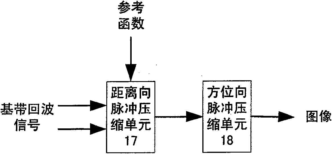
A synthetic aperture radar system using chaos signal comprises base band chaos signal generator, orthogonal modulator, the first and the second intermediate band-pass filter and amplifier, the first and the second mixer, power amplifier, low noise amplifier, coherent rectifier, A / D converter, data recorder, imaging processor, timer, frequency source, duplexer and antenna for easily clearing off noise signal and raising width of mapping belt.

Description

technical field [0001] The invention belongs to a synthetic aperture radar system, in particular to a synthetic aperture radar system using nonlinear frequency modulation signals, noise signals and chaotic signals. Background technique [0002] The high resolution of the traditional synthetic aperture radar (SAR) in the range direction is obtained by the pulse pressure of the linear frequency modulation signal (LFM), but the LFM signal is not easy to achieve waveform agility, because when using the synthetic aperture radar, multiple The radar signal p(t), the enemy can train its adaptive signal processor to obtain a better estimate of p(t) based on these signals, in order to counteract this signal estimate, the radar signal p( t) To confuse the enemy's receiving radar, this is the pulse diversity technology. The random noise signal is irrelevant at every moment, and it has the characteristics of pulse diversity. It has been used in the synthetic aperture radar to improve th...

Claims


Application Information

Patent Timeline
Patent Type & Authority Patents(China)
IPC IPC(8): G01S13/90
Inventor 丁凯杨汝良
Owner INST OF ELECTRONICS CHINESE ACAD OF SCI
Learn More