
Preware measuring method based on linear phase position reversal development

A technology of wavefront measurement and linear phase, applied in the field of optical information measurement, can solve problems such as error of wavefront detection results, reduction of light energy utilization, and inconsistent performance

Inactive Publication Date: 2009-12-23
INST OF OPTICS & ELECTRONICS - CHINESE ACAD OF SCI
View PDF4 Cites 0 Cited by
  • Summary
  • Abstract
  • Description
  • Claims
  • Application Information

AI Technical Summary

Problems solved by technology

In applications such as astronomical adaptive optics, the incident light energy of a star target is very weak, any light splitting will reduce the utilization rate of light energy, and if there is a difference between the two imaging systems after splitting (for example, the performance of the two imaging systems is inconsistent) , will bring additional error to the wavefront detection results

Method used

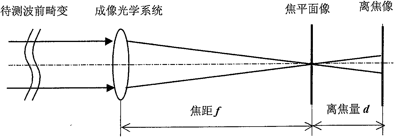
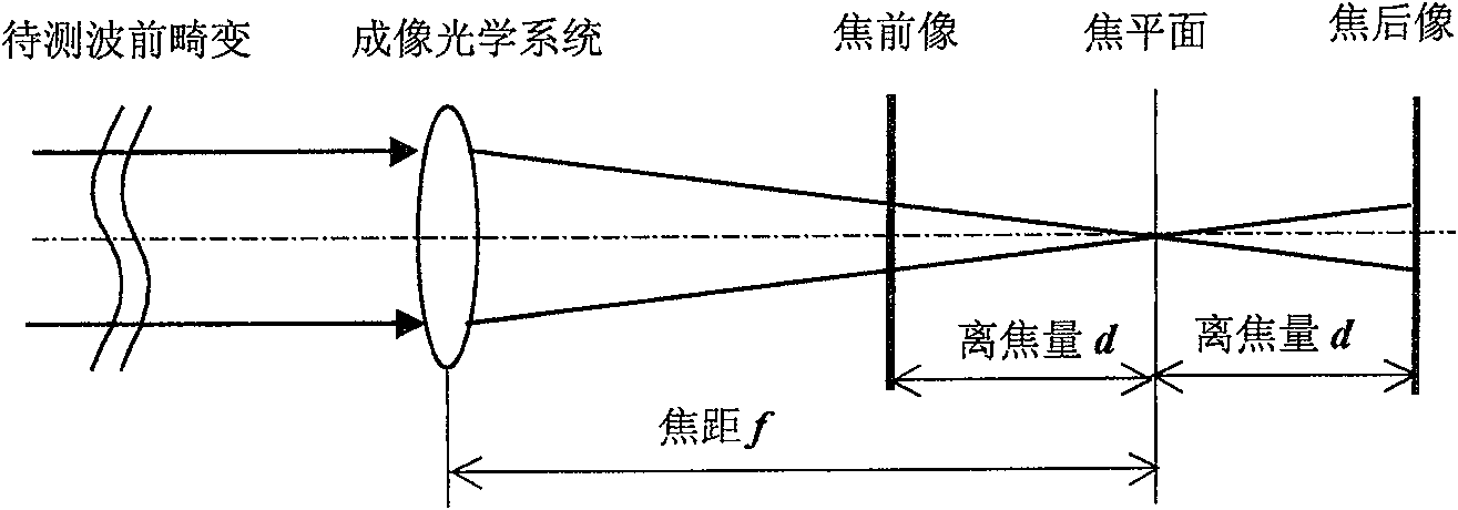

Image

  • Preware measuring method based on linear phase position reversal development
  • Preware measuring method based on linear phase position reversal development
  • Preware measuring method based on linear phase position reversal development

Examples


Embodiment Construction

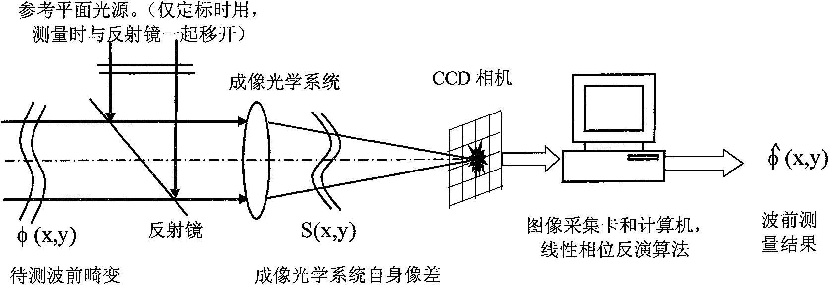
[0078] Such as image 3 As shown, the wavefront sensor used in the method of the present invention is composed of a diffraction imaging optical system, a focal plane imaging device (such as a CCD camera), an image acquisition card, and a computer, and is characterized by the Zernike polynomial commonly used in the field of wavefront aberration measurement The optical wavefront distortion at the entrance pupil that is disturbed by the atmosphere, the Zernike coefficients of the aberrations to be measured are arranged in a predetermined order (generally in the order of spatial frequency from low to high) as a vector a, the purpose of wavefront measurement That is, the value of the coefficient vector a corresponding to the aberration to be measured is obtained.

[0079] The wavefront distortion φ(x,y) to be measured is imaged on the focal plane after passing through the diffraction imaging optical system. A CCD camera is placed near the focal plane to record the far-field image of the...


PUM


Abstract

The invention relates to a kind of wave front measure method basing on the linearity phase conversion. It calibrates to get the recovery matrix of the corresponding relation between the relative change values of the sensor far field light intensity and the coefficient in the incidence wave front, according to the parameters of the wavelength of the lamp-house, the focus of the sensor, the image element of the imaging device and so on. The sensor is calibrated by non-astigmation ideal plane before used. The non-astigmation far field image is regarded as the base image. Measure the incidence beam containing the aberration wave front to get the far field image in this condition. It detracts the base image to get the D-value of the light intensity distribution and form light intensity D-value as predefined. The recovery matrix multiplies the light intensity D-value to get the coefficient of the aberration wave front. The invention possesses the advantages of high energy utilization ratio, little calculation and rapid calculating speed. It can be applied in the high real-time requirement field, for example, self-adaptation optics.

Description

Technical field [0001] The invention belongs to the technical field of optical information measurement, and relates to a method for measuring the wavefront of an incident light beam, in particular to a novel wavefront measurement method based on linear phase inversion. Background technique [0002] In applications such as adaptive optics and optical inspection, it is necessary to measure the wavefront of the beam. Especially in adaptive optics systems, it is necessary to quickly measure wavefront information for real-time control of the wavefront. At present, many methods of measuring wavefront have been developed, such as shear interferometry, Hartmann method, phase inversion method and curvature detection method. These methods have their own advantages and disadvantages and are suitable for their respective applications. Among them, the phase inversion method and the curvature detection method are both imaging-based wavefront measurement methods, which are particularly suitable...

Claims


Application Information

Patent Timeline
Patent Type & Authority Patents(China)
IPC IPC(8): G01J9/00
Inventor 李新阳李敏
Owner INST OF OPTICS & ELECTRONICS - CHINESE ACAD OF SCI
Learn More