Signal polarity detection device and associated method
A signal polarity and detection device technology, applied in the direction of electromagnetic field characteristics, can solve the problems of phase imbalance, unsatisfactory wireless radio frequency signal receiver, and difficult to achieve in the field of analog signals
- Summary
- Abstract
- Description
- Claims
- Application Information
AI Technical Summary
Problems solved by technology
Method used
Image
Examples
Embodiment Construction
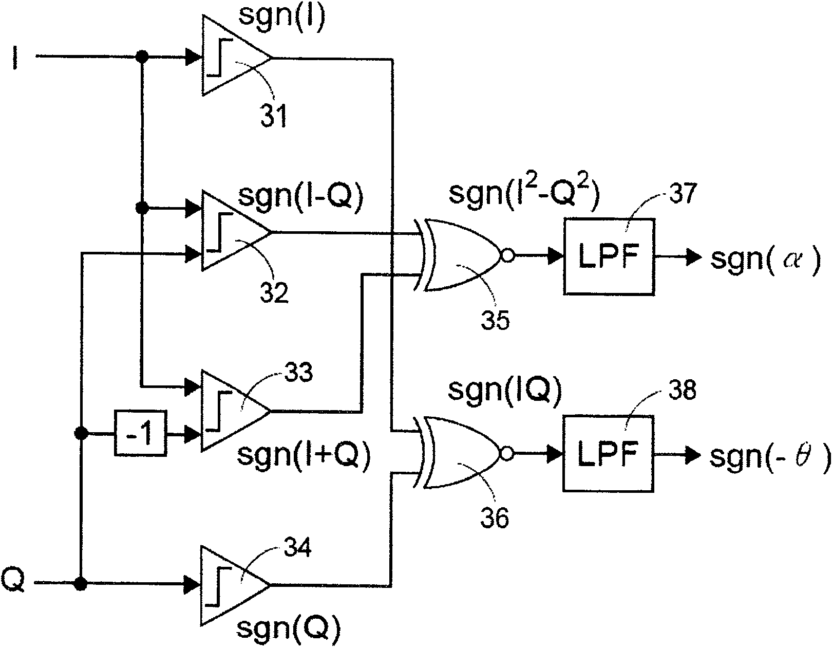
[0045] image 3 A functional block diagram for detecting an imbalance between a signal I and a signal Q is shown. Assuming that α represents the gain mismatch value, and θ represents the phase mismatch value, and when α is much smaller than 1 and θ is small, the signal I and signal Q can be expressed by the following formulas:
[0046] I=(1+α)cos(ωt+θ)
[0047] Q=sin(ωt)
[0048] The product of signal I and signal Q can be expressed as:
[0049] I · Q = ( 1 + α ) cos ( ωt + θ ) · sin ( ωt )
[0050] = ( 1 + α ) ( cos ( ωt ) ...
PUM
 Abstract
Description
Claims
Application Information
 - R&D
- Intellectual Property
- Life Sciences
- Materials
- Tech Scout
- Unparalleled Data Quality
- Higher Quality Content
- 60% Fewer Hallucinations
Browse by: Latest US Patents, China's latest patents, Technical Efficacy Thesaurus, Application Domain, Technology Topic, Popular Technical Reports.
© 2025 PatSnap. All rights reserved.Legal|Privacy policy|Modern Slavery Act Transparency Statement|Sitemap|About US| Contact US: help@patsnap.com


