
Bidirectional constant flux gear pump

A constant flow, gear pump technology, used in pumps, pump control, rotary piston pumps, etc., to solve problems such as inability to provide time, high manufacturing costs for radial piston pumps, and operational limitations

Inactive Publication Date: 2009-10-28
孙玉清 +1
View PDF5 Cites 0 Cited by
  • Summary
  • Abstract
  • Description
  • Claims
  • Application Information

AI Technical Summary

Problems solved by technology

Although some gear pumps can realize two-way rotation, they can only work in the preset rotation direction after they are put in place at the work site, because after the rotation direction is reversed, the oil inlet and outlet ports need to be changed to work. It will affect its normal work, especially when the positive and negative directions are frequently alternated, and it is impossible to provide time and opportunity to adjust the position of the oil inlet and outlet
At present, only radial piston pumps can meet the above requirements for hydraulic pumps that can realize two-way rotation and do not need to change the position of the oil inlet and outlet (that is, keep the position of the inlet and outlet unchanged). The manufacturing cost of the plunger pump is very high, and the operation is limited at high speed, usually not allowed to exceed 1800r / min

Method used


Image

  • Bidirectional constant flux gear pump
  • Bidirectional constant flux gear pump
  • Bidirectional constant flux gear pump

Examples


Embodiment Construction

[0023] The present invention is described in further detail below in conjunction with accompanying drawing:

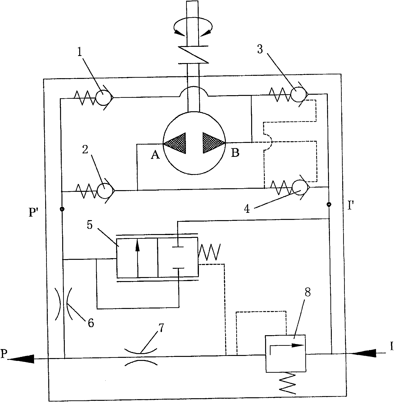
[0024] Such as figure 1 As shown, it is a working principle diagram of the bidirectional constant flow control device of the present invention. When the gear pump rotates in the forward direction, port A absorbs oil and port B discharges oil. Port A absorbs oil to generate negative pressure, and under the action of atmospheric pressure, the second hydraulic control check valve 4 is opened, while the second check valve 2 is closed, so that the gear pump can absorb oil from the oil pump inlet I'; B port discharges oil, the first The hydraulic control check valve 3 is closed, and the oil can only be output to the outlet point P' of the oil pump through the first check valve 1; when the oil discharged from the B port passes through the first check valve 1, a small oil pressure must be established, This pressure can control the second hydraulically controlled one-way valv...


PUM


Abstract

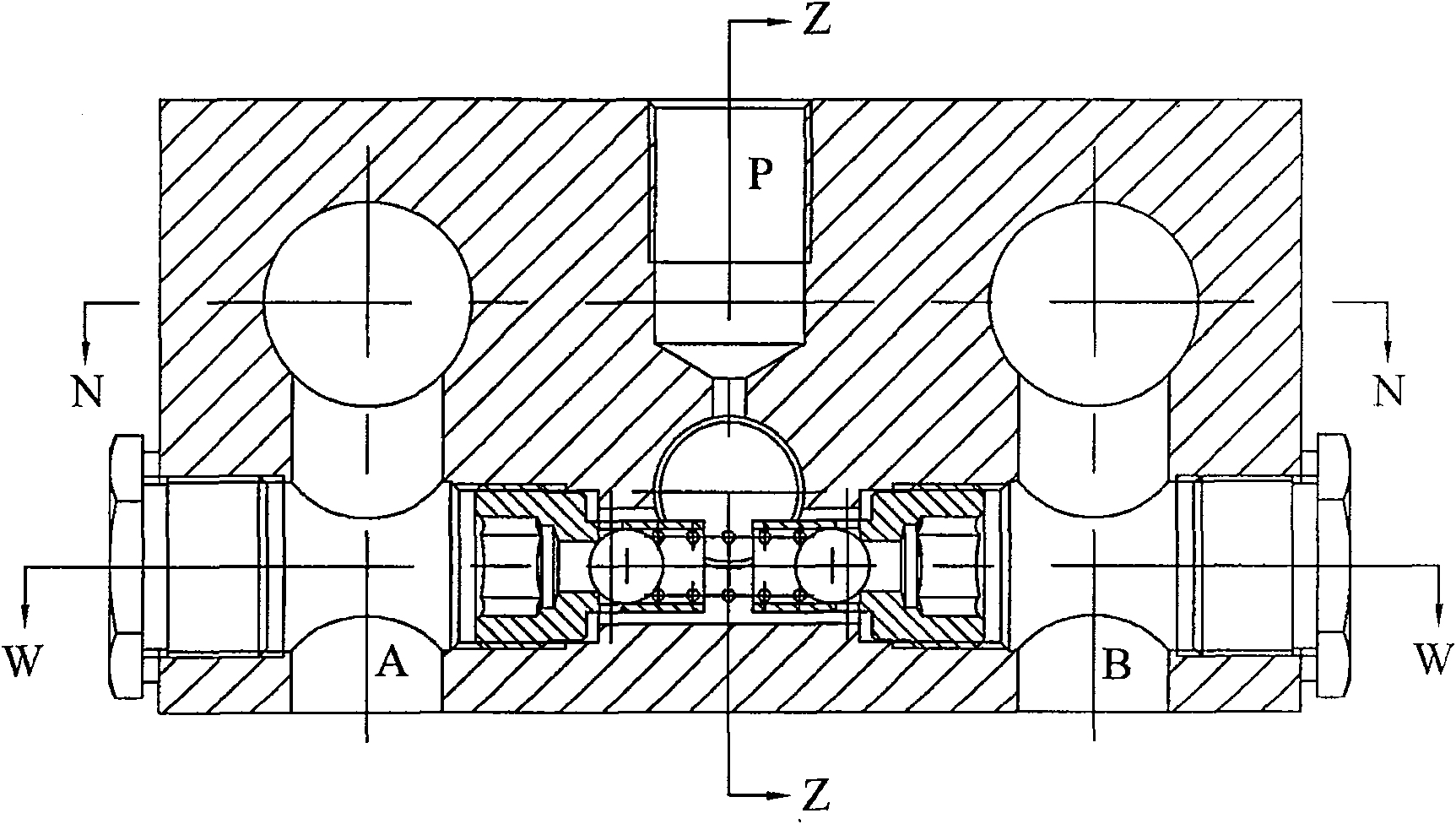
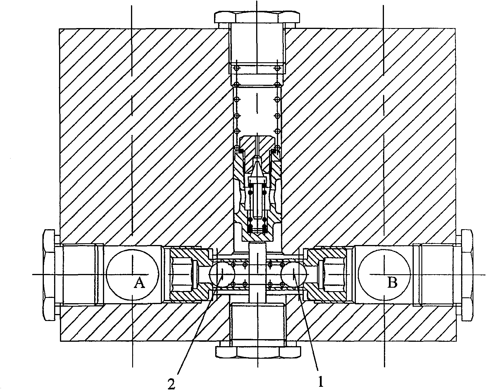
The invention provides a double direction constant flow gear pump, which relates to the technical field of double direction rotation of hydraulic pump. The gear pump mainly comprises a double direction constant flow control device, a general oil pump inlet (I), a general oil pump outlet (P), an oil pump inlet (I'), an oil pump outlet (P'), a normative hydraulic pump oil port (A) and a normative hydraulic pump oil port (B). The double direction constant flow control device comprises a one-way valve (1), a one-way valve (2), a hydraulic control one-way valve (3), a hydraulic control one-way valve (4), a slide valve (5), a flow control orifice (6), a pressure control orifice (7), a cone valve (8), a hydraulic control piston (9) and a hydraulic control piston (10). The invention has the advantages that: when the gear pump rotates in two direction, the constant flow gear pump can keep the position of the oil inlet and oil outlet unchanged, at the same time, maintain constant output flow and realize safe restriction for the output pressure.

Description

technical field [0001] The invention relates to the technical field of bidirectional rotation of hydraulic pumps, in particular to a bidirectional constant flow gear pump. Background technique [0002] Conventional hydraulic pumps usually only have one working direction of rotation. If it is necessary to work in the opposite direction, the relevant parts in the hydraulic pump must be replaced or re-assembled before they can rotate in the other direction. After being in place, it can only work in the preset direction of rotation. Although some gear pumps can realize two-way rotation, they can only work in the preset rotation direction after they are put in place at the work site, because after the rotation direction is reversed, the oil inlet and outlet ports need to be changed to work. It will affect its normal work, especially when the positive and negative directions work alternately frequently, and it will not be able to provide time and opportunity to adjust the positio...

Claims


Application Information

Patent Timeline
Patent Type & Authority Patents(China)
IPC IPC(8): F04C2/18F04C14/24
Inventor 孙玉清侯训波
Owner 孙玉清
Learn More