Vacuum-pumping method and apparatus thereof

A vacuuming device and vacuuming technology, which is applied to liquid variable volume machinery, machines/engines, mechanical equipment, etc., can solve the problems of low utilization rate of heat energy, difficult to operate, and reduce the vacuum degree of the interlayer, and achieve high utilization rate of heat energy. , not easy to run off, the effect of reducing manufacturing costs

Active Publication Date: 2009-10-28
CIMC VEHICLES (GROUP) CO LTD
View PDF5 Cites 4 Cited by
  • Summary
  • Abstract
  • Description
  • Claims
  • Application Information

AI Technical Summary

Problems solved by technology

Although this method can achieve the vacuum degree required by the specification, because the vacuum itself has thermal insulation properties, it is difficult for external heating to transfer heat to the thermal insulation material, and the entire heating replacement vacuum pumping process takes a long time; The gas is filled into the interlayer for heating and replacement, such as a method for vacuuming a liquefied natural gas storage tank for replacing air disclosed in CN03152769.8, but this method has a low thermal energy utilization rate and is not easy to operate. It is only used for containers with low vacuum requirements and does not Suitable for high vacuum multi-layer insulation containers
The above two methods all need to spend a lot of manpower, material resources and financial resources, and the manufacturing cost is very high, and the cryogenic liquid storage tanks, tank boxes and tank trucks manufactured by the existing vacuum technology, the moisture in the insulating material in the interlayer It is difficult to completely remove, and the remaining moisture will continuously release water vapor after vacuum sealing, resulting in a gradual decrease in the vacuum degree of the interlayer and a decrease in thermal insulation performance

Method used


Image

  • Vacuum-pumping method and apparatus thereof

Examples


Embodiment Construction

[0024] Hereinafter, preferred embodiments according to the present invention will be described with reference to the accompanying drawings.

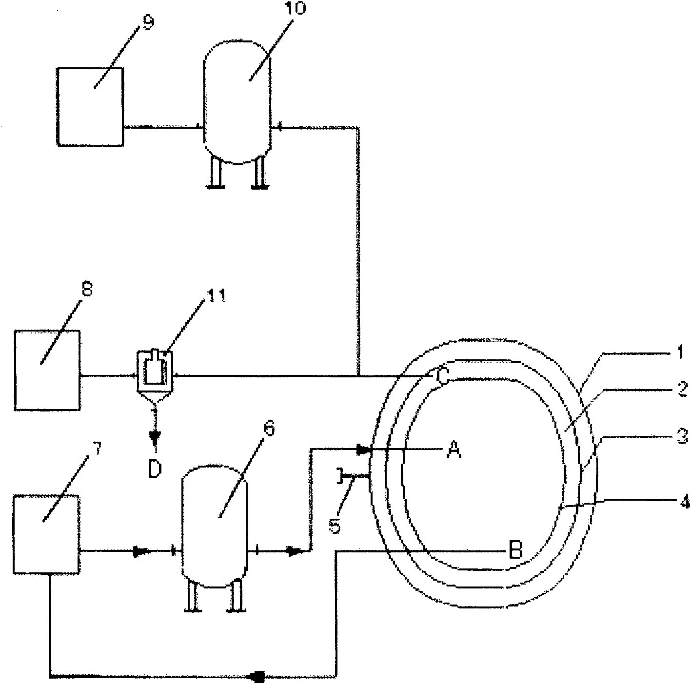
[0025] Such as figure 1 As shown in FIG. 2 , it is a schematic structural diagram of a vacuum pumping device according to a preferred embodiment of the present invention. The vacuum device according to the present invention is used to evacuate the interlayer between the outer cylinder and the inner cylinder of the multilayer heat insulation container, wherein the interlayer between the outer cylinder and the inner cylinder is filled with heat insulating material, and the high vacuum multilayer heat insulation container It can be used in cryogenic storage tanks, tank boxes or tank cars. The vacuum pumping device comprises: a first gas conveying device 7, which has an air outlet; a first gas heater 6, whose inlet is connected with the gas outlet of the first gas conveying device 7, and whose outlet is connected with the air inlet of the i...


PUM


Abstract

The invention discloses a vacuuming method and a device thereof, which are used for vacuuming the interlayer between the outer cylinder and the inner cylinder of a multilayer heat-insulating container. Wherein the vacuum pumping device comprises: a first gas conveying device, which has a gas outlet; a first gas heater, whose inlet is connected with the gas outlet of the first gas conveying device, and whose outlet is connected with the air inlet of the inner cylinder pass; vacuum unit, which communicates with the interlayer; the second gas delivery device, which has a gas outlet; the second gas heater, whose inlet is connected with the gas outlet of the second gas delivery device, and whose outlet is connected with the interlayer connected. By adopting the vacuum pumping method and its device of the present invention, the vacuum pumping time of multi-layer thermal insulation storage tanks, tank containers, and tank trucks is shortened from 7-15 days to 3-6 days, which greatly shortens the time for high-vacuum multi-layer thermal insulation storage tanks. , tank container, tank car manufacturing cycle, reducing manufacturing costs.

Description

technical field [0001] The invention relates to a vacuum pumping method and its device, in particular to a vacuum pumping method and its device which can significantly improve the vacuum pumping efficiency and vacuum degree. Background technique [0002] Cryogenic liquid storage tanks, cryogenic liquid tanks, and cryogenic liquid tank trucks for storage of liquid nitrogen, liquid oxygen, liquid hydrogen, liquid argon, and liquefied natural gas that require extremely high insulation performance at home and abroad, the insulation form is mostly high-vacuum multi-layer insulation , the vacuum degree must be below 0.03Pa absolute pressure. For cryogenic liquid storage tanks of tens of square meters, the vacuuming time of the interlayer itself is very long, and because the heat insulating material in the interlayer has strong air absorption and large suction resistance, the moisture absorbed in the heat insulating material is difficult to extract. There are two common existing ...

Claims


Application Information

Patent Timeline
Patent Type & Authority Patents(China)
IPC IPC(8): F04B37/06F04B37/14
Inventor 施才兴唐家雄童杰东杨进
Owner CIMC VEHICLES (GROUP) CO LTD
Why Eureka
Try Eureka