
High angle drill at blast furnace casting port

A blast furnace tapping and high-angle technology, which is applied to blast furnaces, blast furnace details, blast furnace parts, etc., can solve the problems of high consumption of drill bits and drill pipes, high labor intensity of workers, and easy falling off of blades, etc., so as to reduce labor intensity, The effect of short opening time and not easy to fall off

Inactive Publication Date: 2009-10-14
YINGKOU HAIYUAN STEMMING MFG
View PDF11 Cites 0 Cited by
  • Summary
  • Abstract
  • Description
  • Claims
  • Application Information

AI Technical Summary

Problems solved by technology

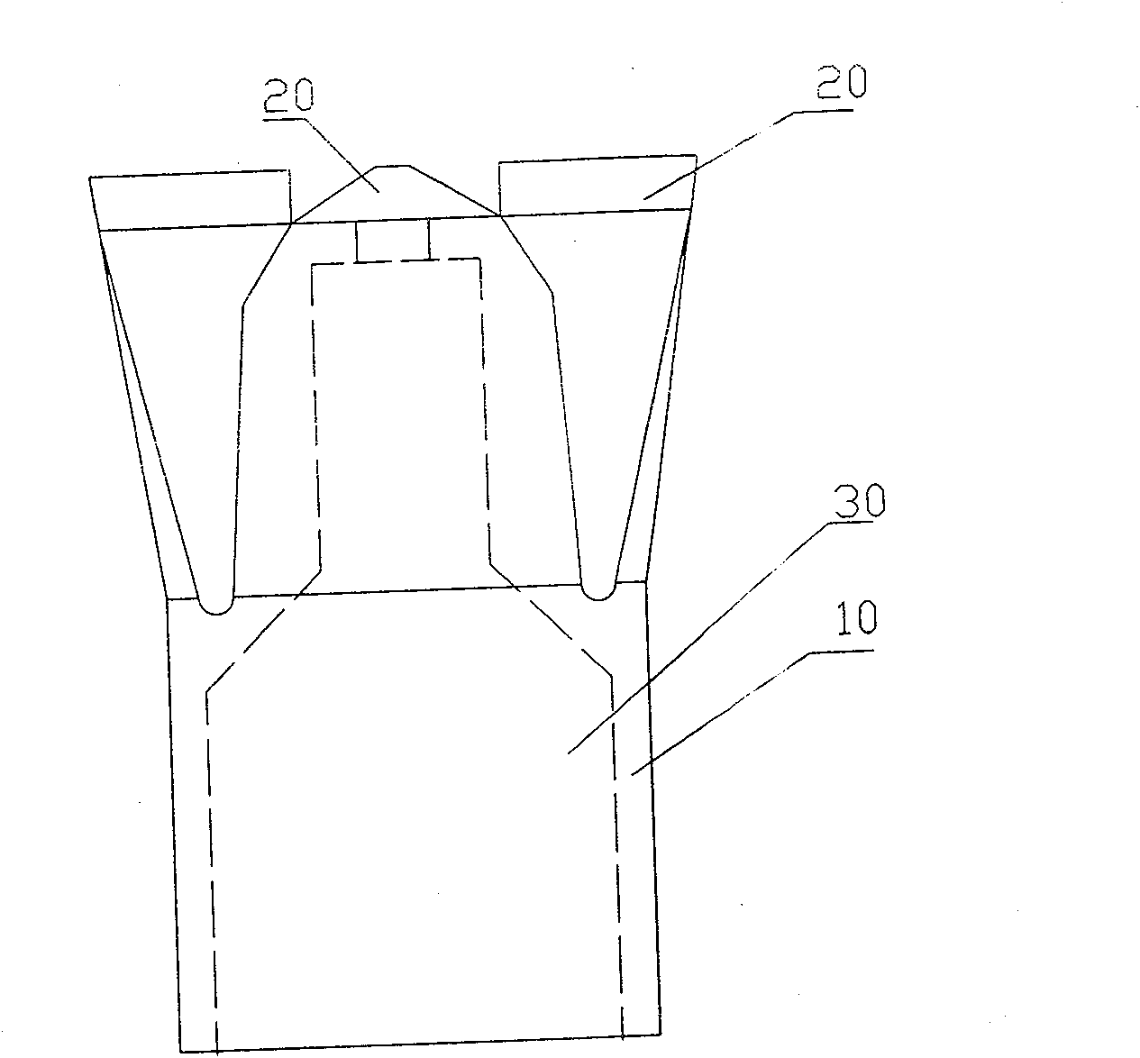
At present, drill bits are used for blast furnace taphole opening, such as figure 1 As shown, most of the blades 20 are directly welded on the upper end of the base 10, and the blades 20 are horizontal, that is, the edges of all blades are on the same horizontal plane, so that when opening, the upper top surface of the blades Stress, plane contact, large resistance, easy to grind the outer corner without turning into a pointed shape, not moving, and the opening time is long. It takes about 20 minutes to open once. When the depth of the iron hole reaches 3 meters, sometimes it even reaches 40 minutes; Since the blade is directly welded on the base, when it reaches the red point, the high temperature melts and the blade melts, and the blade is also easy to fall off due to vibration when opening, and multiple drill bits and drill pipes need to be replaced, such as a For a blast furnace with a taphole depth of 3 meters, 3 to 5 drill pipes and drill bits are required to drill the taphole for one opening; this results in high labor intensity for workers, slag and iron in the furnace, and large consumption of drill bits and drill pipes, resulting in waste

Method used


Image

  • High angle drill at blast furnace casting port
  • High angle drill at blast furnace casting port
  • High angle drill at blast furnace casting port

Examples


Embodiment Construction

[0019] Further illustrate the present invention below in conjunction with accompanying drawing.

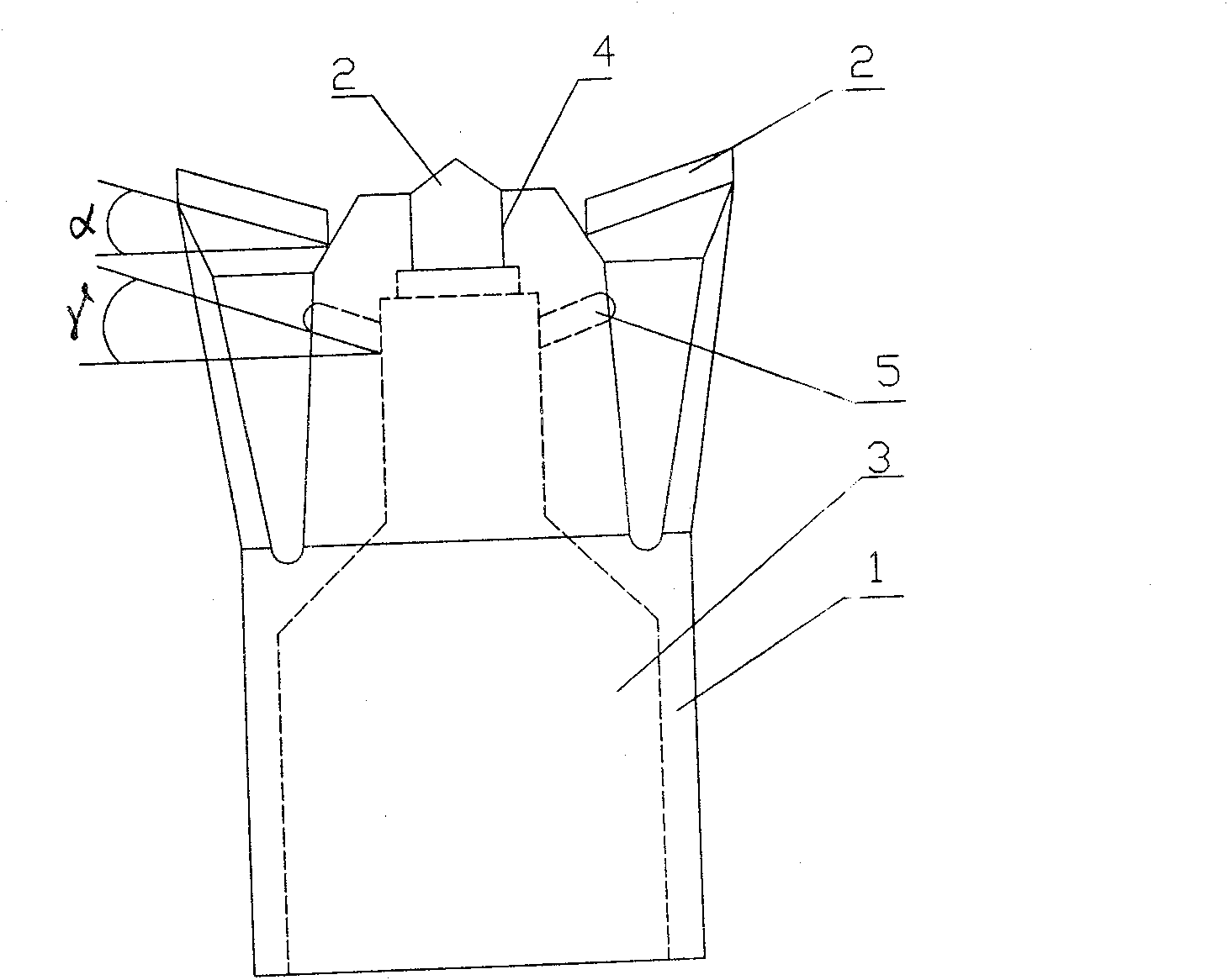
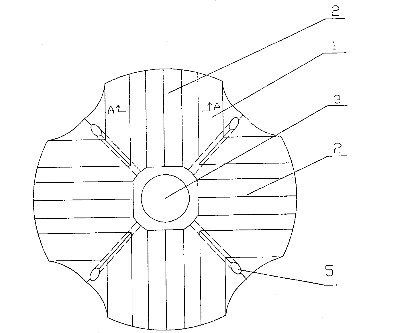
[0020] like Figure 2~3 As shown, a high-angle drill bit for a blast furnace taphole is composed of a base 1, a blade 2, a main air hole 3, a knife groove 4 and a side air hole 5.

[0021] The center of the base 1 is provided with a main air hole 3, and the upper end of the base 1 is evenly made into four wings, and the upper top of the wing is inclined to the main air hole 3 in the center of the base 1, that is, the upper top surface of the wing is in line with the base. The horizontal axis forms an angle α, and α is 7°; a sipe 4 is formed in the center of each wing, and the width of the sipe 4 is 8 mm; as Figure 4 As shown, the blade 2 is welded in the sipe 4, the body of the blade 2 coincides with the sipe 4, the edge is higher than the sipe 4, and the blade angle between the two hypotenuses of the blade is β, and β is 110 °; side vents 5 are provided on the side wall of the...


PUM


Abstract

The invention relates to a high-angle drill set on a blast furnace iron mouth. The technical proposal is introduced below: the high-angle drill comprises a base and a blade knife; the center of the base is provided with a main ventage and the base top is uniformly made into three to five wings with top surfaces inclining towards the base center with an angle of Alpha. The middle of each wing is provided with a knife trough; the blade knife is welded in the knife trough; the knife body shape is in accordance with the knife trough while the knife edge is higher than the trough. The two hypotenuses on the knife edge form an angle of Beta. The sidewall of the base between each wing is provided with a side ventage which is connected with the main ventage and inclines to the main ventage with an angle of Gamma. By the invention, the invention only needs at most two drill bits and drill pipes to open a three meters high furnace and within two to three minutes the iron mouth can be opened too. The technology can not only lower the application cost, but also decrease the labor intensity of workers significantly. Additionally, due to the short time of iron mouth opening, the quantity of iron slag remaining in the furnace is decreased.

Description

Technical field: [0001] The invention relates to the field of a drill bit, in particular to a drill bit used for a drill pipe of a blast furnace taphole opening machine. Background technique: [0002] The iron slag tapping operation in front of the blast furnace is a very important link in the blast furnace production, and the timely opening of the blast furnace to exhaust the iron slag is the key. At present, drill bits are used for blast furnace taphole opening, such as figure 1 As shown, most of the blades 20 are directly welded on the upper end of the base 10, and the blades 20 are horizontal, that is, the edges of all blades are on the same horizontal plane, so that when opening, the upper top surface of the blades Stress, plane contact, large resistance, easy to grind the outer corner without turning into a pointed shape, not moving, and the opening time is long. It takes about 20 minutes to open once. When the depth of the iron hole reaches 3 meters, sometimes it eve...

Claims


Application Information

Patent Timeline
Patent Type & Authority Patents(China)
IPC IPC(8): C21B7/12
Inventor 王恩余
Owner YINGKOU HAIYUAN STEMMING MFG
Learn More