
Expansion-type reflection mirror

A mirror and cable technology, applied in electrical components, antennas, etc., can solve the problems of difficult to use mirrors, difficult to predict film-like structures, surface deformation of inflated films, etc., to improve design reliability, reduce deformation sensitivity, The effect of suppressing changes in tension

Inactive Publication Date: 2009-09-16
NIPPON TELEGRAPH & TELEPHONE CORP
View PDF5 Cites 2 Cited by
  • Summary
  • Abstract
  • Description
  • Claims
  • Application Information

AI Technical Summary

Problems solved by technology

Therefore, the tension of the stretched mirror easily causes the deformation of the surface of the inflated film, and it is difficult to predict the behavior of the membranous structure, so it is difficult to predict its positional deviation relative to the power supply part located far away, which means that it is difficult to mount the mirror the role of the problem
[0017] In particular, when the reflective mirror is formed with an inflated film surface, the position of the mirror portion cannot be accurately determined while the film surface is inflated.
In addition, since it is affected by gravity on the ground, it is important to predict the shape by analyzing the state of weightlessness on the satellite orbit, etc., but it is difficult to predict the shape of the surface of the film with high accuracy with the current analysis technology
In particular, the unfolded mirror itself needs to be supported in some way, but there is a problem that it is difficult to predict the positional relationship between the support position and the mirror surface when the film surface is supported

Method used


Image

  • Expansion-type reflection mirror
  • Expansion-type reflection mirror
  • Expansion-type reflection mirror

Examples


Embodiment Construction

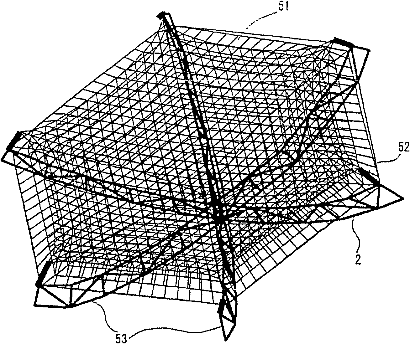
[0050] figure 1 It is a perspective view showing a structural example (1) of the expansion mirror of the present invention. In the figure, the unfolded reflector of this structural example is formed into a mirror shape by hanging the cable network 51 on the unfolded truss 53 through the stay nails 52 . For example, when the cable network 51 is used in a predetermined shape as a reflector of a large-scale spread antenna installed on a communication satellite, the mirror portion takes a parabolic shape, and transmits and receives electromagnetic waves through a power supply unit (not shown) arranged at the focal point. .

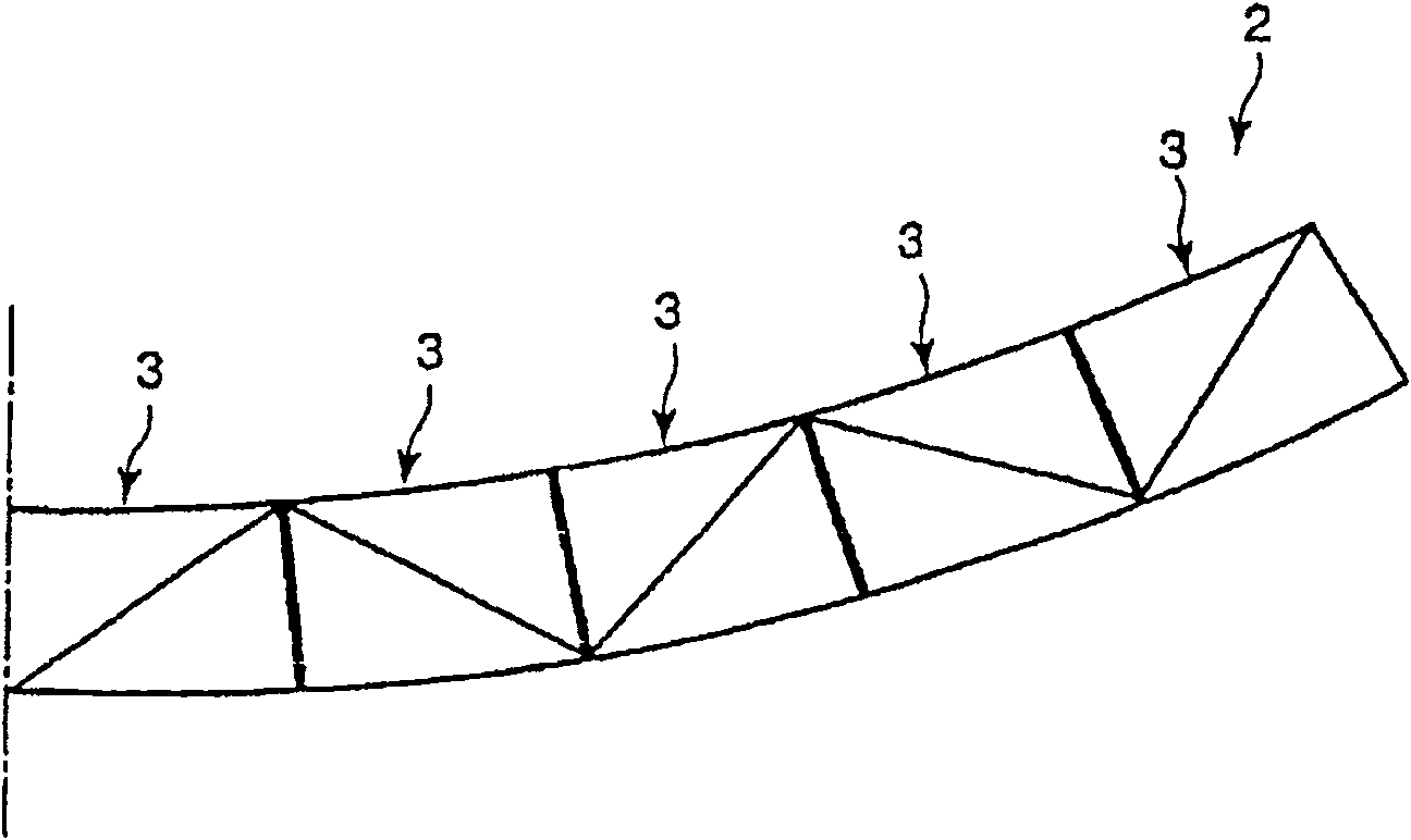
[0051] The unfolding trusses 53 are arranged radially by connecting the bottom ends of a plurality of (here, six) frames 2 (expandable members), and can be folded or unfolded with the bottom ends as rotation points. In the folded state, the occupied volume becomes smaller, and in the unfolded state, it forms a predetermined shape. A tension nail 52 is prov...


PUM


Abstract

The unfolded reflector of the present invention has a connecting device, which is erected between a plurality of telescopic parts constituting the unfolded truss, and connects the part corresponding to the antinode of the buckling mode and the part corresponding to the node, and the buckling mode is Created on telescoping members when tension is applied to surface cables. In addition, the surface cable is composed of the inner surface cable and the outer peripheral surface cable bonded to its outer periphery. The inner surface cable uses a cable with high rigidity and less length change due to tension changes. A cable with low rigidity and small tension changes due to length changes. The inner surface cables are tensioned from the unfolded trusses through the outer peripheral surface cables to form a predetermined mirror shape.

Description

technical field [0001] The present invention relates to an unfolded reflector which is mounted on an artificial satellite or the like in a folded state and unfolded in outer space. In particular, it relates to an unfolded reflector which occupies a small volume in a folded state and forms a predetermined shape in an unfolded state. Background technique [0002] Rockets such as Ariana and H-IIA are used to transport deployed antennas mounted on artificial satellites and the like to outer space. However, the cargo storage space of the rocket is limited, so when transporting a large unfolded antenna, it is stored in the rocket in a small folded state, and the unfolded antenna is unfolded after the rocket reaches space. . Among the spread mirrors constituting such a spread antenna, there is a reflector that combines a plurality of basic structures to form a large spread antenna according to the number of the basic structures. [0003] Figure 13 A structure example of a conve...

Claims


Application Information

Patent Timeline
Patent Type & Authority Patents(China)
IPC IPC(8): H01Q15/20
Inventor 原田聪目黑在石川博规小泽悟
Owner NIPPON TELEGRAPH & TELEPHONE CORP
Learn More