
Looping tool strickle and its manufacturing method

A technology of loop forming tool and manufacturing method, which is applied in textiles and papermaking, knitting, warp knitting, etc., and can solve the problems of increasing manufacturing costs, etc.

Inactive Publication Date: 2009-09-09
KARL MAYER TEXTILMASCHFAB GMBH
View PDF9 Cites 4 Cited by
  • Summary
  • Abstract
  • Description
  • Claims
  • Application Information

AI Technical Summary

Problems solved by technology

[0006] However, the consequence of this approach is that the knitting elements must be subjected to another processing step, which increases manufacturing costs

Method used


Image

  • Looping tool strickle and its manufacturing method
  • Looping tool strickle and its manufacturing method
  • Looping tool strickle and its manufacturing method

Examples


Embodiment Construction

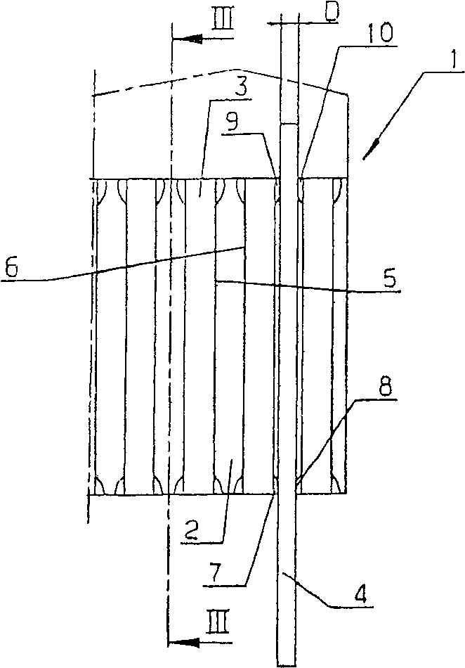
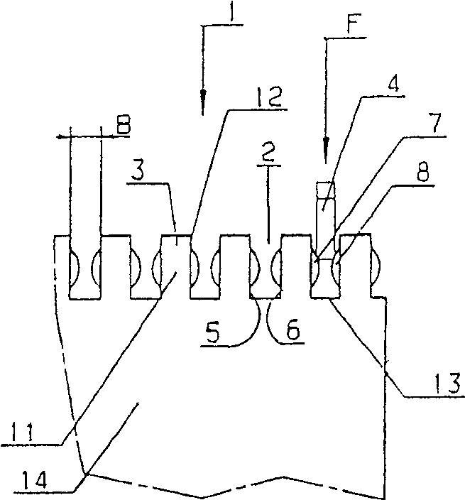
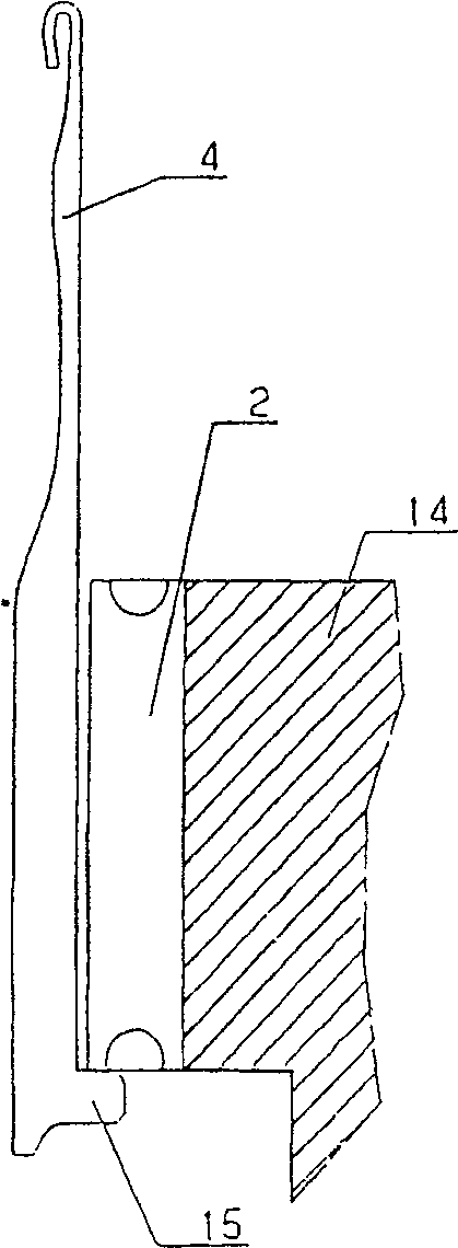
[0030] A looping tool bar 1 has a plurality of grooves 2 separated from one another by webs 3 . The slots 2 are used for accommodating knitting tools, a crochet needle 4 being inserted here as an example into a slot.

[0031] Each groove 2 has two side walls 5 , 6 , wherein the side walls 5 , 6 form the sides of the web 3 .

[0032] as by figure 1 with 2 It can be seen that the thickness D of the hook 4 is smaller than the width B of the groove 2 .

[0033] In order to be able to hold the hooks 4 in their grooves 2 virtually without play, the webs 3 have formed parts 7 - 10 on their two front sides. These shaped parts 7-10 are formed by upsetting of the material. For this purpose, a tool-in the simplest case is a continuous flat material on the length of the looping tool bar 1, its height is less than the height of the spacer 3-attached to each end face of the spacer 3, A predetermined force is then applied, for example by impact. A cutout 11 is now formed at the end fac...


PUM


Abstract

A looping tool bar (1) is proposed, which has a plurality of grooves (2) arranged side by side, which grooves are separated from each other by spacers (3) and into which knitting elements (4) can be inserted, The groove (2) has side walls (5, 6) whose spacing is greater than the thickness (D) of the knitting element (4). It is desirable to be able to achieve high precision when assembling the knitting elements. For this reason, the groove (2) has an elastically deformable molding (7-10) on at least one side wall (5, 6) respectively, which makes the distance to the opposite wall (6, 5) reduced to Less than the thickness (D) of the knitting element (4).

Description

technical field [0001] The invention relates to a looping tool bar (Wirkwerkzeugbarre), which bar has a plurality of grooves arranged side by side, which grooves are separated from each other by spacers, and knitting elements can be inserted in these grooves, wherein the grooves have side walls, the spacing of which is greater than the thickness of the knitting element. Furthermore, the invention relates to a method for producing a looping tool bar having a plurality of grooves arranged next to one another and separated from one another by webs. Background technique [0002] A loop forming tool bar of the type mentioned at the outset is known from DE 44 14 703 C2. [0003] One such loop forming tool bar is used in warp knitting machines. The looping tool bars carry a number of knitting elements, such as crochet hooks, side by side. The knitting elements are fixed in the grooves so that they can resist lateral forces to a defined extent. Since the knitting element sometim...

Claims


Application Information

Patent Timeline
Patent Type & Authority Patents(China)
IPC IPC(8): D04B27/24D04B27/06
CPCD04B27/06
Inventor J·哈拉塞克
Owner KARL MAYER TEXTILMASCHFAB GMBH
Learn More