
Dust aspirator motor

A vacuum cleaner and motor technology, which is applied in the installation of vacuum cleaners, suction filters, motor fan assemblies, etc., can solve the problems of complex mold making of the front bracket, affecting the working life of the vacuum cleaner, and worsening the performance of the vacuum cleaner, etc. Compact structure and the effect of reducing loss

Inactive Publication Date: 2009-09-09
金马达制造厂有限公司
View PDF6 Cites 0 Cited by
  • Summary
  • Abstract
  • Description
  • Claims
  • Application Information

AI Technical Summary

Problems solved by technology

The defects in the vacuum cleaner motor device in the prior art are: 1. There are a plurality of fins for guiding the wind formed on the front bracket, which makes the mold making of the front bracket quite complicated, so the cost is high; and because of the fins , There are gaps and unevenness after the front bracket and the air deflector are assembled and connected, and the airflow cannot be guided smoothly to the air outlet, resulting in high noise and low work efficiency; 2. Between the front bracket and the air deflector, and between the front bracket and the air deflector No sealing measures are taken between the shaft sleeves. When the vacuum cleaner is working, the dust and liquid will inevitably seep into the gap between the output shaft of the motor and the front bracket under the action of high pressure, and even into the motor, resulting in poor performance or even damage to the vacuum cleaner. , affecting the working life of the vacuum cleaner

Method used


Image

  • Dust aspirator motor
  • Dust aspirator motor
  • Dust aspirator motor

Examples


Embodiment Construction

[0018] Below in conjunction with the best embodiment shown in the accompanying drawings, it will be further described in detail.

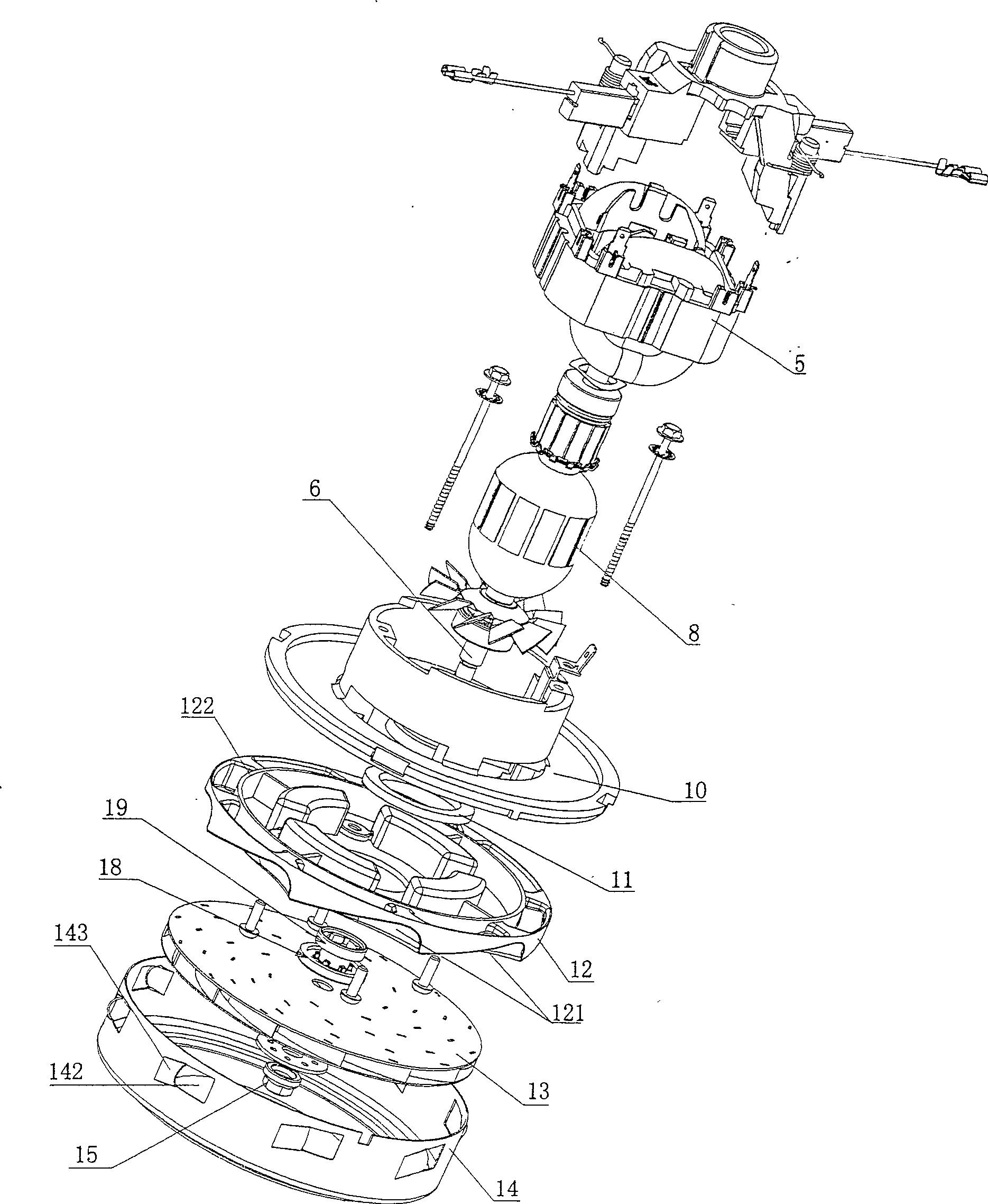
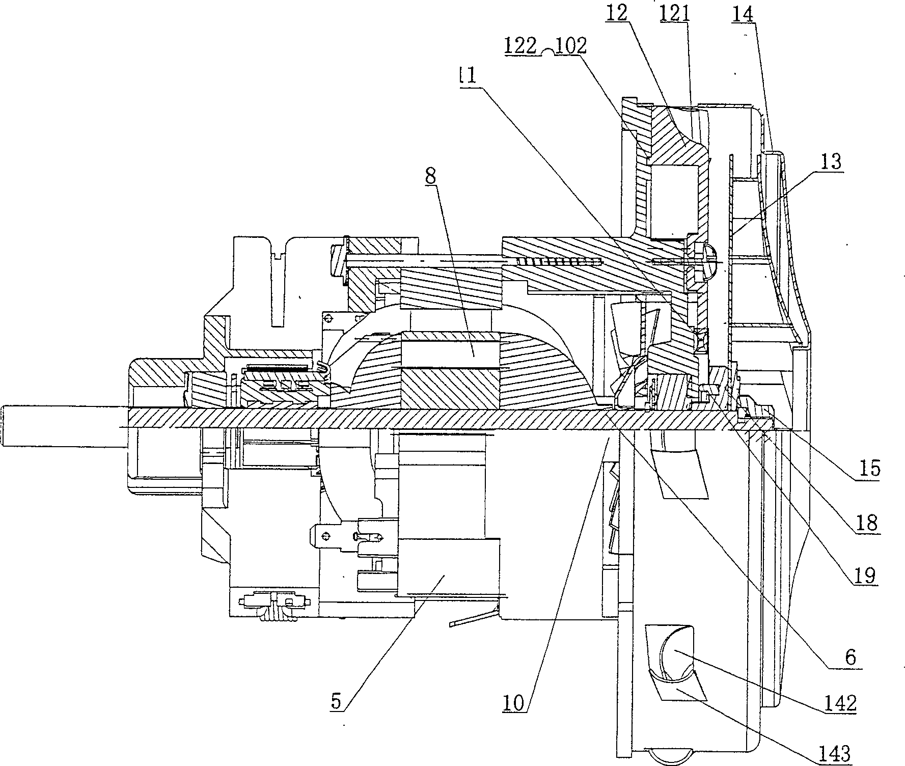
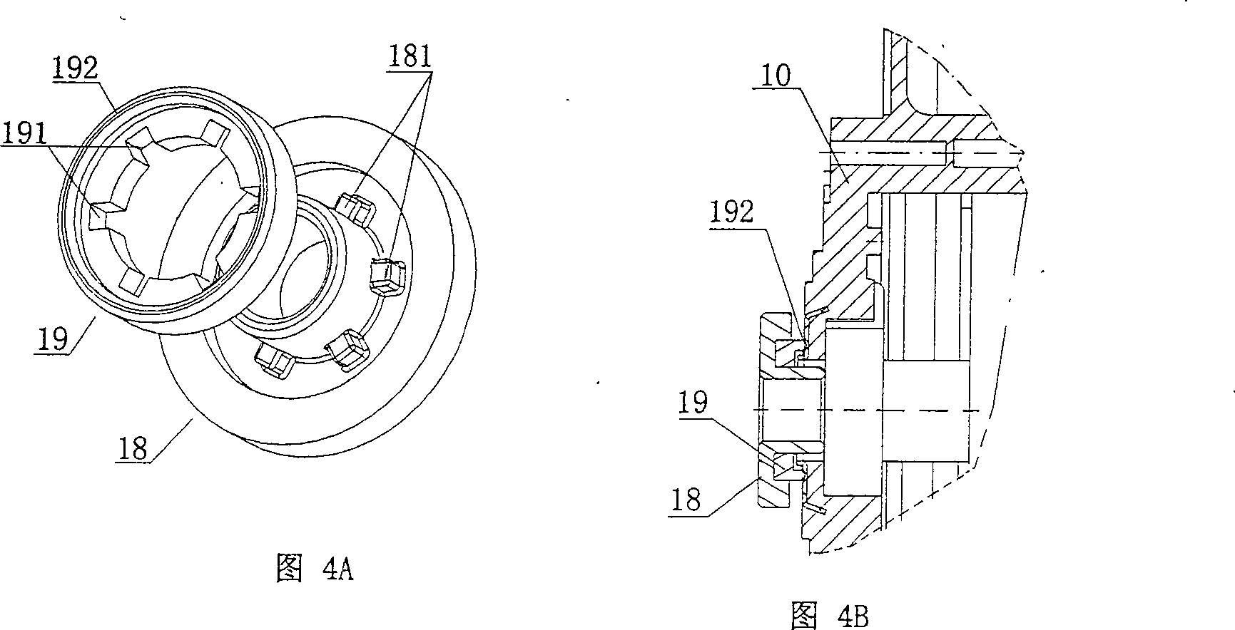
[0019] The vacuum cleaner motor device of the present invention, such as figure 1 and figure 2 As shown, it includes a motor assembly and a diffuser assembly; the motor assembly includes a stator 5, a rotor 8, an output shaft 6, and a front bracket 10; the diffuser assembly includes a wind deflector 12, a centrifugal wind wheel 13 and a windshield 14; The front end of the windshield 14 is an air inlet, and a plurality of air outlets 142 are arranged around; Centrifugal wind wheel 13; the output shaft 6 is provided with a shaft sleeve 18 at the place just protruding from the front bracket 10, so that the output shaft 6 is rotatably supported on the front bracket 10. Such as Figure 1 to Figure 3 As shown, the front bracket 10 is generally in the shape of a hollow cylinder, and most of its outer peripheral flange is an annular plane 101, and the ...


PUM


Abstract

The invention relates to a motor device for a vacuum cleaner. The diffuser assembly includes a wind deflector, a centrifugal wind wheel and a wind cover; the front end of the wind cover is an air inlet, and a plurality of air outlets are arranged around; the output shaft of the motor passes through the front bracket and the wind guide in sequence. The front end of the output shaft fixes the centrifugal wind wheel with the help of nuts; the output shaft is provided with a sleeve at the position just protruding from the front bracket, so that the output shaft is rotatably supported on the front bracket; the front bracket is generally hollow Cylindrical, most of its outer peripheral flange is an annular plane, and the front side of the annular plane is provided with an annular groove; the rear side of the wind deflector is provided with an annular protrusion matching the annular groove, and the annular protrusion is embedded in the In the annular groove; the front end surface of the air deflector is formed with an air flow channel from the inside to the periphery to guide the air flow axially away from the centrifugal fan wheel. The technical effect of the invention lies in: simplified structure, low manufacturing cost; reduced noise, improved work efficiency; low noise, high stability and the like.

Description

technical field [0001] The invention relates to structural parts of a vacuum cleaner, in particular to a motor device specially used for a bypass type dry / wet vacuum cleaner. Background technique [0002] The bypass type dry / wet vacuum cleaner motor device generally includes a motor assembly and a diffuser assembly; the motor assembly includes a stator, a rotor, an output shaft, and a front bracket; the diffuser assembly includes a wind deflector, a centrifugal fan wheel and a wind cover; The front end of the windshield is an air inlet, surrounded by a plurality of air outlets; the output shaft of the motor passes through the front bracket, the wind deflector and the centrifugal wind wheel in turn, and is finally fixed at the windshield; the output shaft just extends Out of the front bracket, a shaft sleeve is provided. The defects in the vacuum cleaner motor device in the prior art are: 1. There are a plurality of fins for guiding the wind formed on the front bracket, whic...

Claims


Application Information

Patent Timeline
Patent Type & Authority Patents(China)
IPC IPC(8): A47L9/00A47L9/16A47L9/22H02K1/12
Inventor 郭骏伟
Owner 金马达制造厂有限公司
Learn More