Disk device

A drive device and disc technology, applied in the direction of reducing the influence of temperature on the carrier, instruments, record carrier structural parts, etc., can solve problems such as errors, adverse effects of support movement, error readout, etc.

Inactive Publication Date: 2009-09-02
SONY CORP
View PDF2 Cites 0 Cited by
  • Summary
  • Abstract
  • Description
  • Claims
  • Application Information

AI Technical Summary

Problems solved by technology

As a result, an error (a recording and / or reading error) may occur when data is recorded to and / or played back from the optical disc 1.
In addition, if the dirt and dust sucked into the disc drive body 6 adhere to and deposit on other parts, such as the guide shaft 46 and the gear train 49 of the stand moving mechanism 47, etc., the movement of the stand will be adversely affected. impact, and are more prone to problems such as causing trouble finding and tracking

Method used


Image

  • Disk device
  • Disk device
  • Disk device

Examples


Embodiment Construction

[0067] The following will refer to the attached Figures 15 to 17 An embodiment of an optical disk drive apparatus employing the present invention will be described. which with Figures 1 to 10 The same structural components in the above all use the same symbols and will not be described again.

[0068] The dustproof structure of the optical disc drive will be described below.

[0069] First combine the Figures 15 to 20 The dust-proof structure of an optical disk drive device 5 will be described.

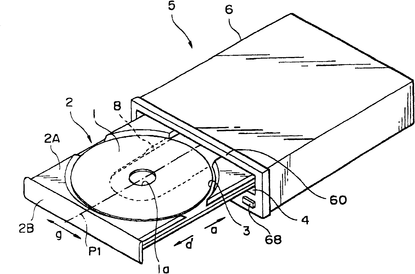
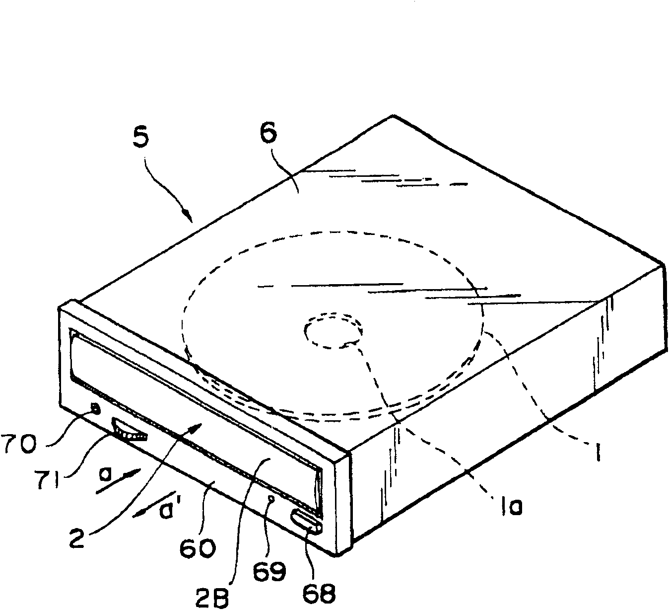
[0070] Such as Figures 15 to 20 As shown, a plurality of elongated air inlets 74 are formed on the front panel 60 of the optical disc drive body 6 , and they are located on a horizontal (horizontal) line along the outside of the lower edge of the tray inlet and outlet 4 . A gap is provided between the lower cover 63 of the disk drive body 6 and the printed circuit boards 64 , 65 to serve as an air intake passage 75 . The front end of the air intake passage 75 (on the side of...


PUM


Abstract

SUMMARY OF THE INVENTION The present invention aims to provide a disk drive device which can reduce the thickness of the entire device and which can smoothly clamp and release a disc-shaped recording device to and from a disk table. The disc driving device of the present invention mainly includes: a disc chuck made of non-magnetic parts, which is supported by a chuck supporting member located above the disk-shaped recording medium, and is held by the magnetic attraction force of the disc worktable. Attracting, supported on the chuck support in a floating state; a magnet embedded in the central portion above the disc chuck and magnetized in the vertical direction, and an upper magnetic member, which is arranged above the disc chuck, When the disc tray is in the ejected state, it is used to attract the disc chuck to reach above the clamped position of the disc-shaped recording medium under the magnetic attraction of the magnet; when the disc-shaped recording medium is in the clamped position, The disk working table is close to the magnet, so that the disk chuck is attracted to the disk working table under the magnetic attraction force of the magnet.

Description

[0001] This application is a divisional application of the Chinese patent application with the application number 98109790.1, the filing date being June 8, 1998, and the title "disk drive device". technical field [0002] The present invention relates to the technical field of disc drive devices, preferably a disc drive device for an optical disc drive device, wherein a disc tray is used to load and eject a disc-shaped recording medium (such as an optical disc, etc.). Background technique [0003] A disc drive of the above type has been proposed in an earlier application filed by the assignee of the present application, and reference will be made below to the attached Figures 1 to 14 Explain it. Such as figure 1 As shown, a recess 3 is formed on the upper surface of the tray body 2A of the disc tray 2, and an optical disc 1 as a disc-shaped recording medium is horizontally placed in a recess 3. As shown in FIG. Then, when the tray front panel 2B of the disc tray 2 is push...

Claims


Application Information

Patent Timeline
Patent Type & Authority Patents(China)
IPC IPC(8): G11B17/04G11B17/02G11B17/028G11B33/14
CPCG11B17/0285G11B17/0282G11B33/142G11B17/0288G11B17/056G11B17/04G11B33/02
Inventor 大森清玉山隆三
Owner SONY CORP
Why Eureka
Try Eureka