
Laser cladding powder spraying machine

A laser cladding and spraying machine technology, applied in laser welding equipment, coating, metal material coating process, etc., can solve problems affecting the laser surface, hindering the health of operators, and difficult to complete spraying equipment

Inactive Publication Date: 2009-09-02
BEIJING DALU TIANRUI LASER ENG TECHCO
View PDF4 Cites 0 Cited by
  • Summary
  • Abstract
  • Description
  • Claims
  • Application Information

AI Technical Summary

Problems solved by technology

Especially for the laser surface treatment process, it is necessary to spray a layer of cladding powder on the workpiece to be surface treated in advance. To complete this fine spraying task, it can only be done manually at present, because manual spraying can be used in all directions. The whole process of spraying is difficult to complete with existing spraying equipment
[0003] Artificial spraying also has serious shortcomings, the main one is uneven coating, which affects the effect of laser surface treatment, which will cause uneven hardness on the surface of the workpiece and affect the use. In addition, the efficiency of spraying is also low, and it also hinders the operator's health. healthy

Method used


Image

  • Laser cladding powder spraying machine
  • Laser cladding powder spraying machine
  • Laser cladding powder spraying machine

Examples


Embodiment

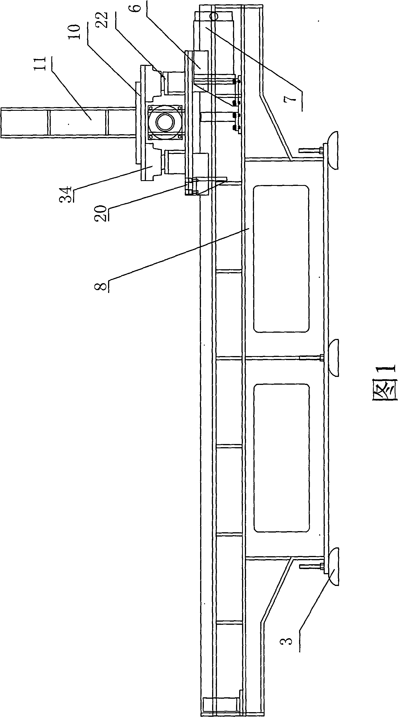
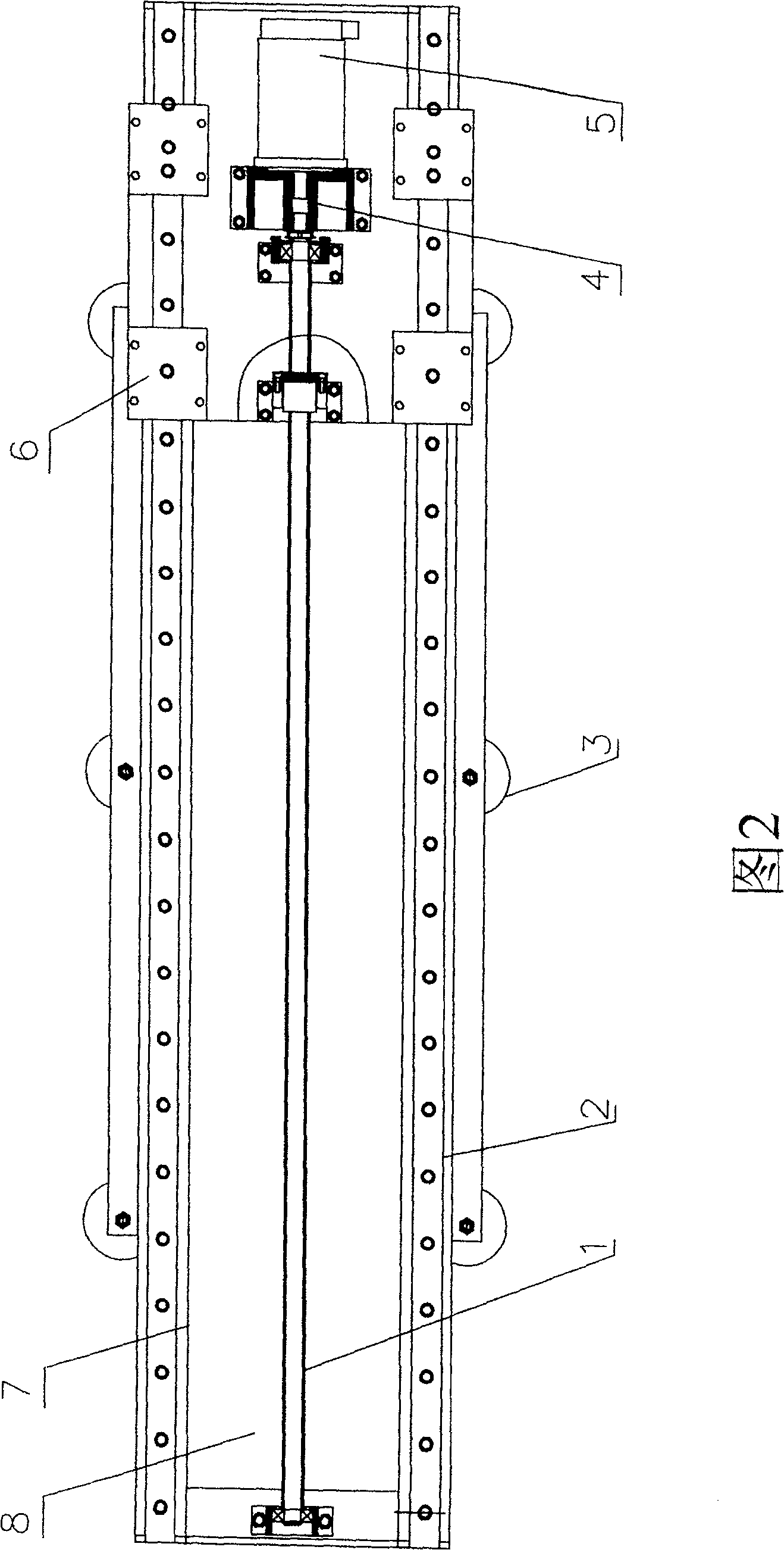
[0023] The laser cladding powder spraying machine includes a machine base, a transmission device, a spraying device, and an air circuit control mechanism. On both sides of the base 8, there are strip-shaped lower rail seats 7, and the lower rail seats 7 are integrated with the base 8. Two linear guide rail pairs 2 are fixedly connected to the upper ends of the lower guide rail seats 7 on both sides with screws.

[0024] The longitudinal ball screw pair 1 is located on the machine base and between the lower guide rail seats 7 on both sides. The two ends of the longitudinal ball screw pair 1 are fixed on the machine base with bearing seats. It is connected in rotation with the longitudinal stepping motor 5 ; the longitudinal ball screw pair 1 is connected in rotation with the nut, and the nut is arranged in the middle of the lower end of the base pedestal 20 below the spray trolley 27 . Four lower sliders 6 that are installed on four corners are fastened under the bottom pedesta...


PUM


Abstract

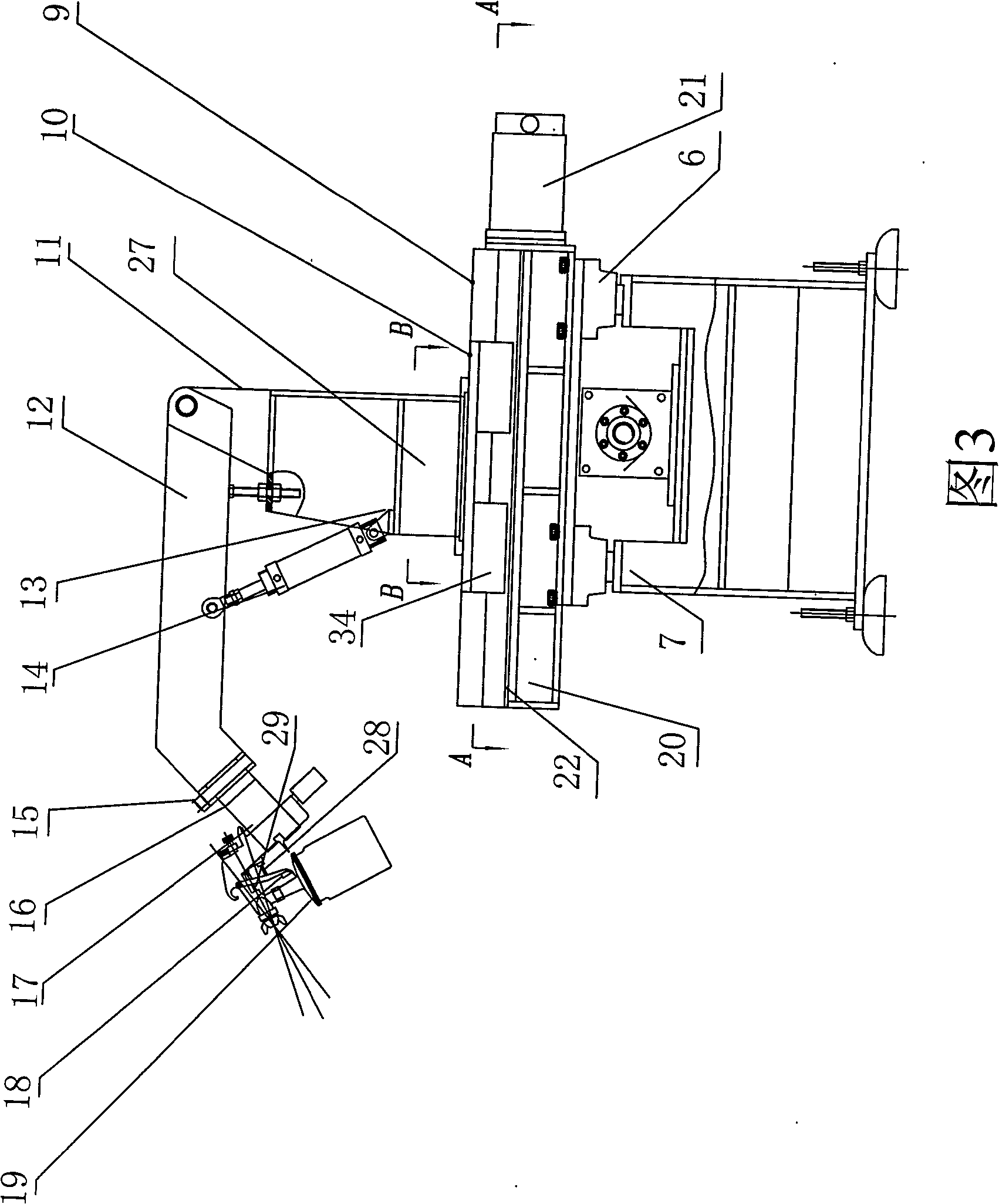
A laser cladding powder spraying machine comprises a transmission device, a spraying device and a gas path control mechanism; a fixed ring is arranged above a base of a spraying car; a rotary ring is connected with the upper part of the fixed ring; a locking keep plate is connected between the fixed ring and the rotary ring; a spraygun vertical wall is fixed on the rotary ring and is in flexible connection with a transverse arm through a pin roll; the middle of the spraygun vertical wall is provided with a cylinder block; the top of a cylinder piston rod is fixed on the middle of the transverse arm. The front end of the transverse arm is provided with an angle adjusting device and is tightly connected with the mounting bracket of a spraygun; a biaxial cylinder and a spraygun are arranged above the mounting bracket; the top of the piston rod in the lower part of the biaxial cylinder is tightly connected with a spray hooker. The invention is skillful in design, reasonable in structure, simple in operation and automatic in the whole machine control; as the spraying car can operate vertically and horizontally and the rotary ring of the base rotates according to specific conditions, the transverse arm can move up and down when spraying; the spraygun can have multi-angle rotation and can complete multi-angle spatial spraying; as the invention has automatic control, uniform spraying, superior quality and high working efficiency, the health of operators can be fully ensured.

Description

(1) Technical field [0001] The invention relates to a spraying machine, in particular to a laser cladding powder spraying machine used for spraying cladding powder on the outer layer of a workpiece before laser surface treatment. (2) Background technology [0002] The exterior of the product or part is almost always sprayed or painted with a protective layer, so as to improve the appearance of the product and prevent the product from rusting. Especially for the laser surface treatment process, it is necessary to spray a layer of cladding powder on the workpiece to be surface treated in advance. To complete this fine spraying task, it can only be done manually at present, because manual spraying can be used in all directions. The whole process of spraying is difficult to complete with existing spraying equipment. [0003] Artificial spraying also has serious shortcomings, the main one is the uneven coating, which affects the effect of laser surface treatment, which will caus...

Claims


Application Information

Patent Timeline
Patent Type & Authority Patents(China)
IPC IPC(8): C23C24/10B23K26/34
Inventor 林青海黄旭东
Owner BEIJING DALU TIANRUI LASER ENG TECHCO
Learn More