For example, British 1 Ltd. (http: / / www.1limited.com) utilizes double-
chip piezoelectric
ceramic sheets to make spirally wound piezoelectric actuators, and the piezoelectric actuators are combined with optical lenses and After the brackets are combined, they can be placed in cameras, digital cameras or camera phones for automatic focusing of images. Although the spiral-wound piezoelectric
actuator has the advantages of small size, large actuation displacement, and low
power consumption However, the
disadvantage is that when winding the two-
chip piezoelectric
ceramic sheet into a helically wound piezoelectric
actuator blank, it must be done manually; even if It is completed using automated tools, and because of the high difficulty and complexity of the manufacturing process, there is a risk of low yield and unstable quality; therefore, the spiral-wound piezoelectric actuator is used in cameras, digital cameras or In camera phones, its industrial applicability is not high
[0003] Furthermore, the early application of ultrasonic motors (or piezoelectric motors) or piezoelectric actuators in traditional cameras is an existing technology, and there are many related patents, such as US Patent Nos. 4,755,705, 4,786,836, and 4,829,209 , 4935659, 4952834, 4959580, 5013982, etc. are all, due to the
large size of the traditional cameras that housed the film in the early days, the existing devices such as the above-mentioned
ultrasonic motor (or
piezoelectric motor) or piezoelectric actuator or existing devices or existing Technology has made optical lenses or used to drive optical lenses, which will not cause too many problems. However, in recent years, digital cameras have gradually replaced traditional cameras, and
mobile phone lenses with
zoom-in or
zoom-out functions have also become fashionable commodities and become Under the trend of the inevitable standard equipment of mobile phones, the above-mentioned large-scale existing ultrasonic motors (or piezoelectric motors) or piezoelectric actuators can no longer be accommodated in them. Currently visible digital cameras or camera phones, other The size of the optical lens module is still very large, and the existing device or existing technology is mainly used
[0004] As for digital cameras or camera phones with small-sized piezoelectric optical lenses, although they can be found in relevant patents, papers or seminars, the components of the existing piezoelectric optical lenses are quite complicated, and the relevant components cannot It is completed by batch precision
processing, which must be processed separately
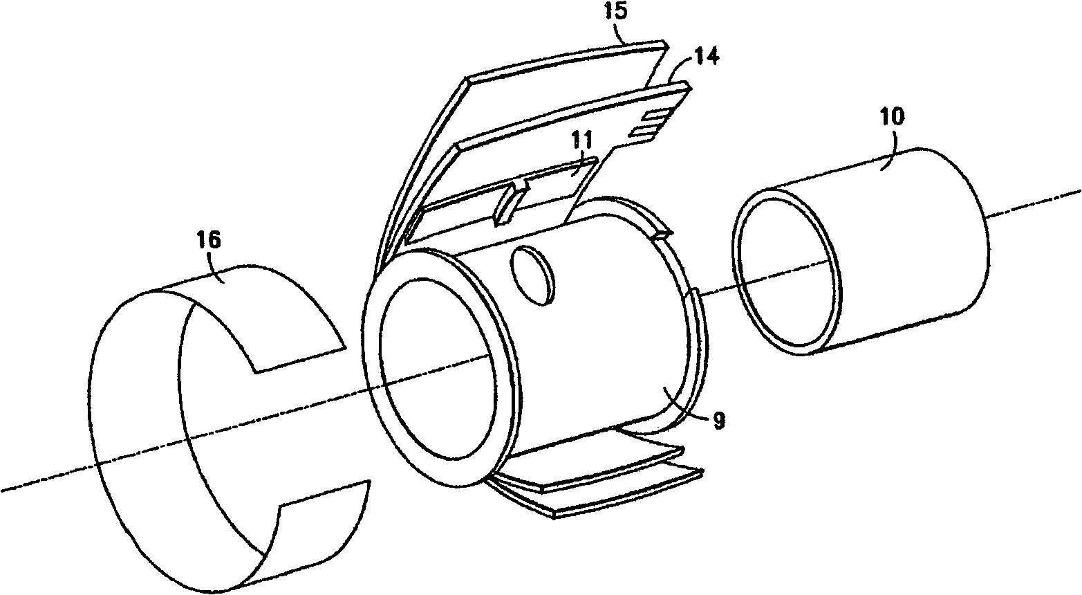
[0005] see figure 1 As shown, U.S. Patent No. 6710950 "Piezoelectric actuator for
digital camera optical
system", the case discloses a structure of an existing piezoelectric optical lens, which mainly includes a support tube 9, and a support tube 9 is provided inside the support tube 9. Lens
barrel 10, the lens
barrel 10 is used to set the optical lens (not shown in the figure), a flexible circuit board 14 is sleeved on the outside of the support tube 9, and the inner side wall of the circuit board 14 extends axially A plurality of piezoelectric actuators 11 are provided (only one group is shown in the figure), and a layer of elastic insulating sheet 15 is coated on the outside of the circuit board 14, and the mirror is driven by the piezoelectric actuators 11.
Barrel 10, but the lack of the structure is that the length of the lens
barrel 10 is based on displacement, its volume is huge, and the circuit control is not easy
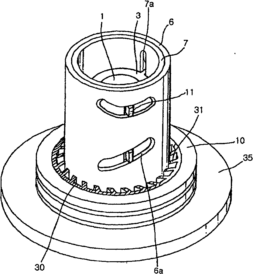
[0006] see figure 2 , U.S. Patent No. 6853507 "Lens driving device", the case discloses an optical lens driving device, which is provided with a round tube 7 on a rear cover 35, and a mirror frame 3 is arranged inside the round tube 7, The picture frame 3 is for setting the optical lens 1, and a sleeve 6 is provided outside the circular tube 7, and the circular tube 7 and the sleeve 6 respectively have guide grooves 6a, 7a for the optical lens 1 to have. The bump 11 is embedded in it at the same time, and a micro gear 30 is arranged on the rear cover 35, and the teeth 31 of the micro gear 31 are embedded in the bottom of the sleeve 6, and then wrapped around the micro gear 30. A circle of piezoelectric actuator 10 is used to sequentially drive the micro gear 30 and the sleeve 6 to rotate through the piezoelectric actuator 10, thereby driving the optical lens 1 on the inner axis of the circular tube 7 However, the lack of the structure is that the structure is quite complicated, and the fabrication of the micro-gear 30 is difficult. At the same time, the piezoelectric actuator 10 must be segmented and polarized, and the cost is very expensive.
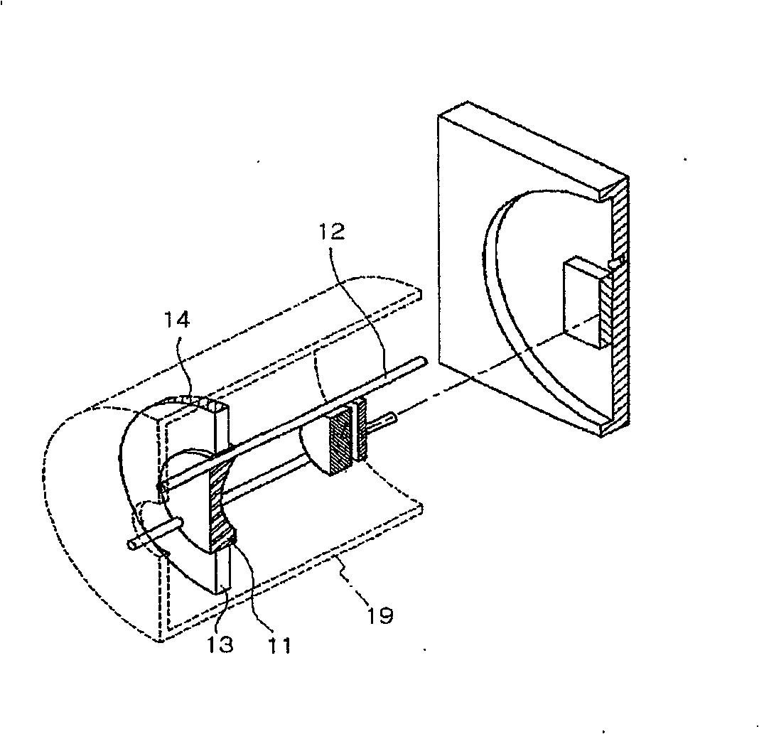
[0007] see again image 3 , Korean Patent Publication No. 1020040078265 "Transfer unit, in whicha lens and an actuator are formed in one body", the optical lens driving device disclosed in the case is provided with a guide rod inside a cylindrical cover 19 12. The piezoelectric component 13 and the support block 14. The
disadvantage of the structure is that a
mass block (
mass) needs to be added to cause inertial force to move, resulting in an increase in the
diameter and weight of the cylindrical cover 19
[0008] Looking at the existing piezoelectric optical lens, its components are quite complicated. In addition to increasing the difficulty of manufacturing and
processing, its
assembly method is also quite complicated, especially the
assembly method of the piezoelectric
stator is not easy, thus detracting from the piezoelectric optical lens. The driving force of the lens, moreover, each small
assembly cannot utilize the automatic
machine to complete, also increased manpower consumption and manufacturing cost in vain, so, although described existing piezoelectric optical lens has the
advantage of small volume, but in cost However, it has no competitive
advantage, so it has no commercial value or industrial applicability


