
Screw and corresponding punch

A technology for screws and punching tools, applied in the direction of screws, nuts, bolts, etc., which can solve problems such as inability to generate sufficient torque, increase in manufacturing costs, and easy damage to grooves and joint blades

Inactive Publication Date: 2018-12-11
世享工业股份有限公司
View PDF6 Cites 0 Cited by
  • Summary
  • Abstract
  • Description
  • Claims
  • Application Information

AI Technical Summary

Problems solved by technology

However, the screwdriver bits that are commonly used with screw drive grooves are usually limited to having corresponding mating blades
For example, the cross-shaped groove is only suitable for providing a cross-shaped joint blade alignment insertion, which is not convenient for the insertion operation
Furthermore, the driving torque point of the cross-shaped joint blade inserted into the cross-shaped groove is small, and sufficient torque cannot be generated, and the groove and the joint blade are easily damaged, reducing the service life
In addition, the combination of the cross-shaped joint blade inserted into the cross-shaped groove does not produce an interference fit. Therefore, if the two can be combined without separation, it is usually assisted by the suction force of a magnet, resulting in an increase in manufacturing costs.

Method used


Image

  • Screw and corresponding punch
  • Screw and corresponding punch
  • Screw and corresponding punch

Examples


Embodiment Construction

[0032] Now will only be an example but not in order to limit the specific embodiment, and with reference to the accompanying drawings, the preferred structural content of the present invention is described as follows:

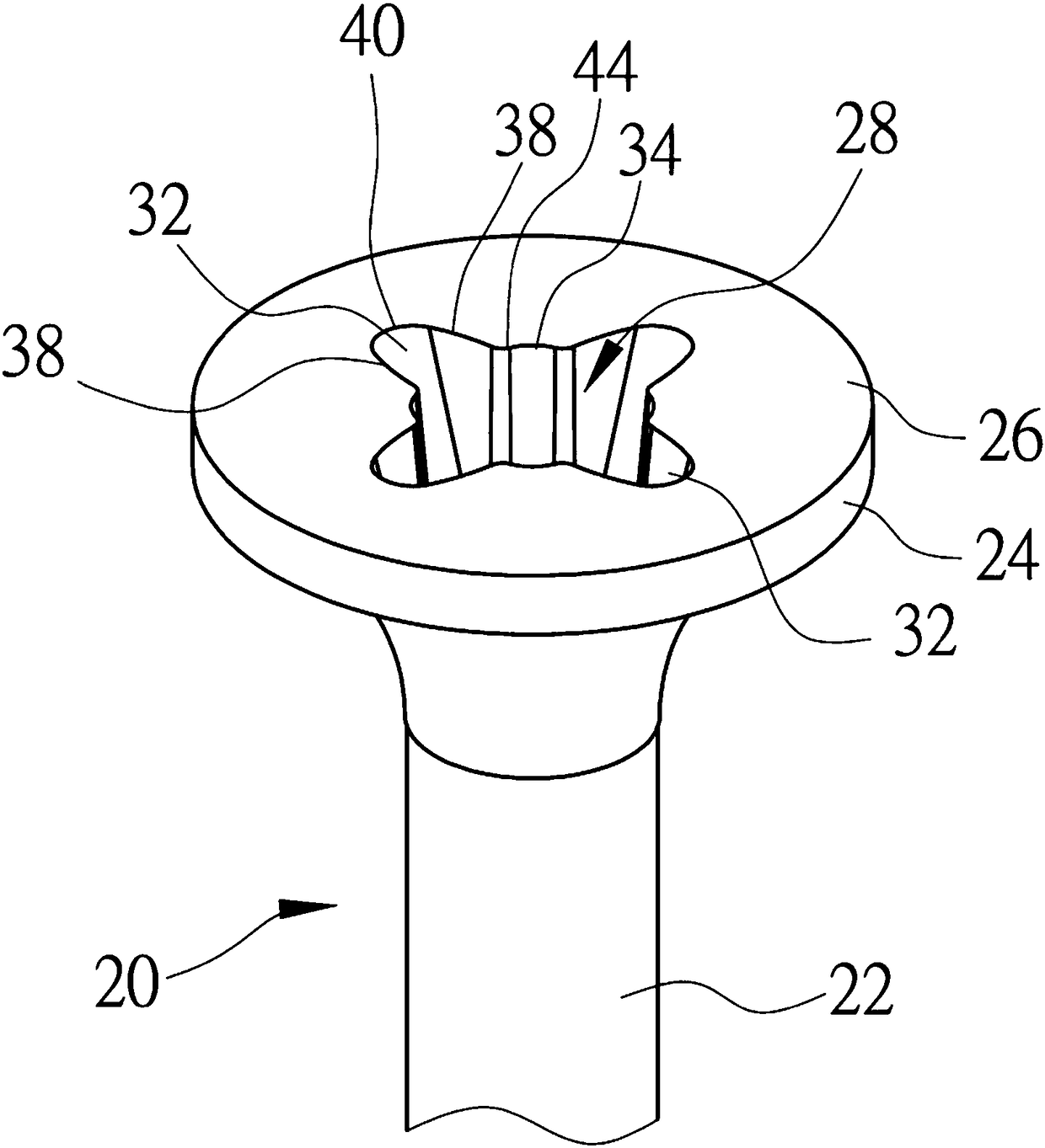
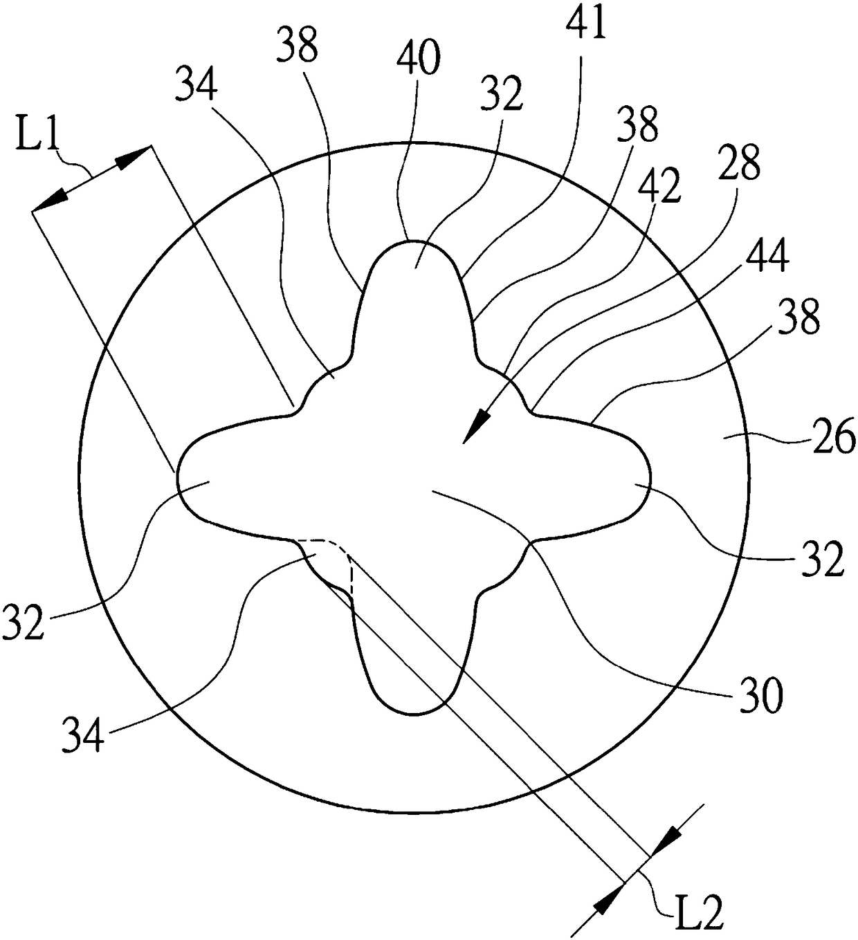
[0033] Figure 2 to Figure 4 A screw 20 according to an embodiment of the present invention is shown. The screw 20 includes a shank 22 and a head 24 formed on the upper end of the shank 22 . Threads (not shown) are provided on the rod body 22 , and a groove 28 is formed on the top surface 26 of the head 24 for providing a combined edge of a tool (such as a bit of a screwdriver) to be inserted to drive the screw 20 to rotate. The groove 28 includes a central region 30 , a plurality of peripheral regions 32 radially extending from the central region 30 , and a plurality of connecting regions 34 connected between the peripheral regions 32 . The central region 30 penetrates into the head 24 to a sufficient depth to provide proper engagement for bit insertion, and ...


PUM


Abstract

Disclosed is a screw. The screw includes a rod body and a head formed at the upper end of the rod body. The top surface of the head is provided with a driving groove. The groove includes a central area, multiple peripheral areas and multiple connecting areas. The central area penetrates into the head and is provided with a groove bottom. The multiple peripheral areas extend radially outward from the central area and separately surround the central area. Each peripheral area is defined by two separated sidewalls and an arc wall connecting the outer ends of the two sidewalls. Each connecting area is connected between the inner ends of the adjacent two sidewalls of the adjacent two peripheral areas. Each connecting area is defined by an arc wall. An arc junction is formed by the two side endsof each arc wall and the inner end of the sidewall of the peripheral area connected to the arc wall. The invention also provides a corresponding punch used for forming the groove of the screw of theinvention.

Description

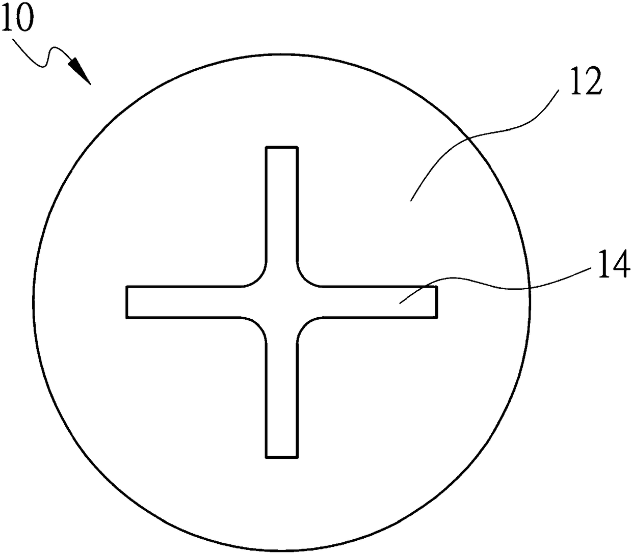
technical field [0001] The present invention relates to a screw with a driving groove on the head and a corresponding punch, especially to a screw whose head groove is substantially cross-shaped or torx-shaped. Background technique [0002] figure 1 A screw head 10 is shown. The top surface 12 of the head 10 has a driving groove 14 for inserting a joint blade (not shown) at the front end of the screw head to drive the screw to rotate. Groove 14 can be figure 1 The cross-shaped shown is or the hole of the type such as inline, square, hexagonal, plum blossom etc. However, conventional screwdriver bits for mating screwdriver bits are generally limited to having corresponding mating edges. For example, the cross-shaped groove is only suitable for aligning and inserting the cross-shaped coupling edge, which is inconvenient for the insertion operation. Furthermore, the driving torque point of the cross-shaped joint blade inserted into the cross-shaped groove is small, which ca...

Claims


Application Information

Patent Timeline
IPC IPC(8): F16B23/00B21D37/10B21D53/24
CPCB21D37/10B21D53/24F16B23/0023F16B23/003
Inventor 蔡家豪
Owner 世享工业股份有限公司
Learn More