Catalyst deterioration detecting apparatus

A degradation detection and catalyst technology, which is applied in the direction of electronic control of exhaust gas treatment devices, diagnostic devices of exhaust gas treatment devices, exhaust gas treatment, etc. Effect of deterioration, prevention of HC and NOx emission, and maintenance of exhaust gas characteristics

Inactive Publication Date: 2009-07-29
HONDA MOTOR CO LTD
View PDF6 Cites 0 Cited by
  • Summary
  • Abstract
  • Description
  • Claims
  • Application Information

AI Technical Summary

Problems solved by technology

Therefore, there is a problem of prolonging the time during which the exhaust gas characteristics deteriorate due to the deterioration detection.

Method used


Image

  • Catalyst deterioration detecting apparatus
  • Catalyst deterioration detecting apparatus
  • Catalyst deterioration detecting apparatus

Examples


no. 1 approach

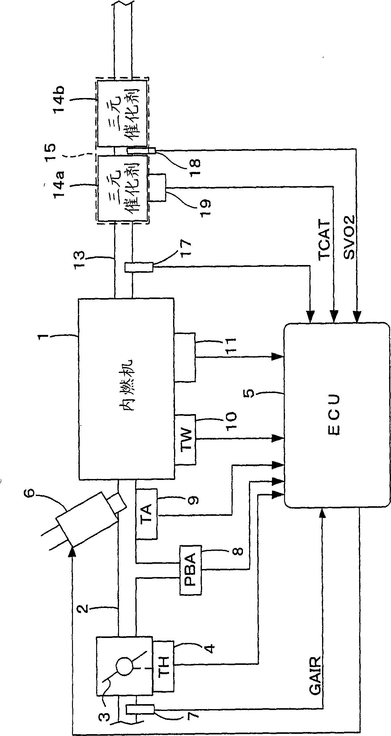
[0042] figure 1 This is an overall configuration diagram of an internal combustion engine (hereinafter referred to as "engine") including a catalyst deterioration detection device according to an embodiment of the present invention and a control device thereof. For example, a throttle valve 3 is arranged in the middle of an intake pipe 2 of a 4-cylinder engine 1 . The throttle valve opening (TH) sensor 4 is connected to the throttle valve 3 , and outputs an electric signal corresponding to the opening degree of the throttle valve 3 to provide to an electronic control unit (hereinafter referred to as “ECU”) 5 .

[0043] The fuel injection valve 6 is provided between the engine 1 and the throttle valve 3 for each cylinder and is slightly upstream of an intake valve (not shown) of the intake pipe 2, and each injection valve is connected to a fuel pump (not shown), and is connected to a fuel pump (not shown). It is electrically connected to the ECU 5, and the opening time of the f...


PUM


Abstract

A deterioration detecting method for a catalyst in an exhaust system of an internal combustion engine (1) for purifying exhaust gases, the system including a first oxygen concentration sensor (17) and a second oxygen concentration sensor (18) disposed, respectively, upstream and downstream of the catalyst (14a). Intake air flow rate of the engine is detected (7). An amount of oxygen flowing into the catalyst (14a) is calculated according to an oxygen concentration detected by the first sensor (17) and the detected intake air flow rate. An air-fuel ratio of an air-fuel mixture supplied to the engine (1) is controlled by alternately switching between lean and rich with respect to the stoichiometric ratio according to a result of comparison between the calculated and target values of the inflowing oxygen amount. A deterioration degree of the catalyst (14a) is detected based on an output of the second sensor (18) when performing the switching control of the air-fuel ratio.

Description

technical field [0001] The present invention relates to a catalyst deterioration detection device for detecting the degree of deterioration of an exhaust gas purification catalyst provided in an exhaust system of an internal combustion engine. Background technique [0002] A technique for determining deterioration of an exhaust gas purification catalyst (hereinafter simply referred to as a "catalyst") provided in an exhaust system of an internal combustion engine is conventionally known. For example, Patent Document 1 discloses a device that measures a first time CB and / or a second time CA, and determines the deterioration of a catalyst based on the first time CB and / or the second time CA, wherein the first time is From the time when the air-fuel ratio of the air-fuel mixture supplied to the internal combustion engine is switched from the lean side to the rich side compared with the stoichiometric air-fuel ratio, the output change of the air-fuel ratio sensor (oxygen concent...

Claims


Application Information

Patent Timeline
Patent Type & Authority Patents(China)
IPC IPC(8): F02D45/00F02D41/14F01N11/00
CPCY02T10/47Y02T10/40
Inventor 末广幸夫饭田润
Owner HONDA MOTOR CO LTD
Why Eureka
Try Eureka