Automobile tyre safety monitoring and deviation prevention system for tyre burst automobile and operation method
What is Al technical title?
Al technical title is built by PatSnap Al team. It summarizes the technical point description of the patent document.
An automobile tire and safety monitoring technology, applied in the field of automobile driving safety intelligent system, can solve the problems such as the increase of the working time of the anti-bias locker, the inability to realize the centralized control of the computer, the time delay and the like
Inactive Publication Date: 2009-06-24
王正键
View PDF6 Cites 0 Cited by
Summary
Abstract
Description
Claims
Application Information
AI Technical Summary
This helps you quickly interpret patents by identifying the three key elements:
Problems solved by technology
Method used
Benefits of technology
Problems solved by technology
However, the disadvantage of the anti-deflection device of the dual-control car tire burst direction is that it can only be installed on the car with the ABS system. If the car is not ABS, the wheel speed sensor must be installed on the wheel; another disadvantage is the anti-deflection lock. The anti-deflection device can only work after the locking rod of the device is inserted into the gap of the locking block. If the steering rod of the car moves slightly, the locking rod can only be inserted into the next gap, which makes the time for the anti-bias lock device to work slightly There is an increase; and the shortcoming of the dual-function hydraulic type automobile tire burst direction anti-deflector is that it cannot realize the centralized control of the computer and the time of action is slightly delayed
[0003] Now, the car tire pressure and temperature alarm device, the central tire inflation and deflation system, and the two kinds of car tire burst anti-deflection devices invented by me can only be installed on the car independently of each other, and their respective advantages and functions cannot be optimized and integrated. The promotion and application of these systems (devices) in automobiles has been affected to a certain extent
Method used
Image
Click on the blue label to locate the original text in one second.
Reading with bidirectional positioning of images and text.
Examples
Embodiment Construction
[0065] Further detailed description will be made below in conjunction with the accompanying drawings and specific embodiments
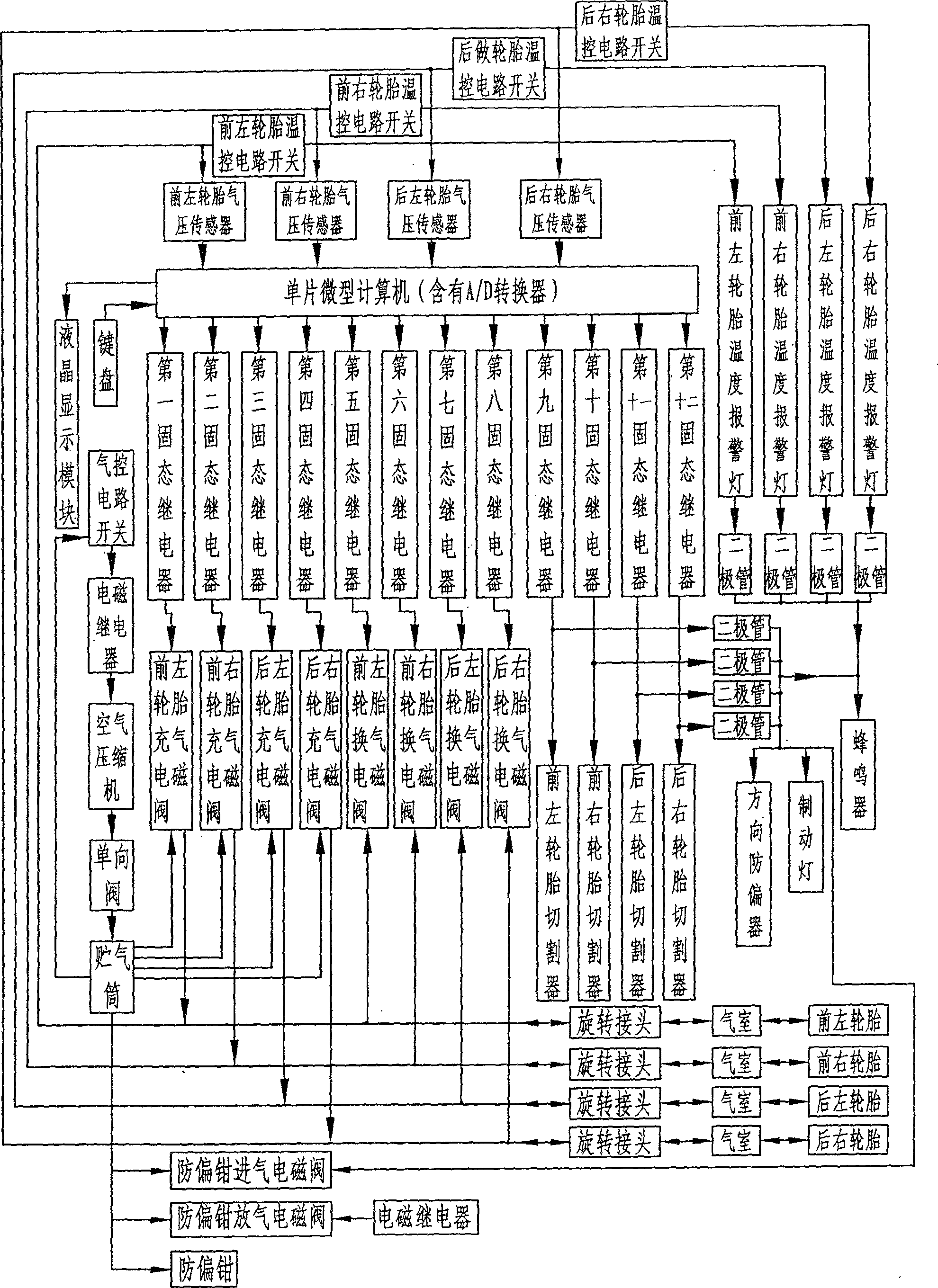
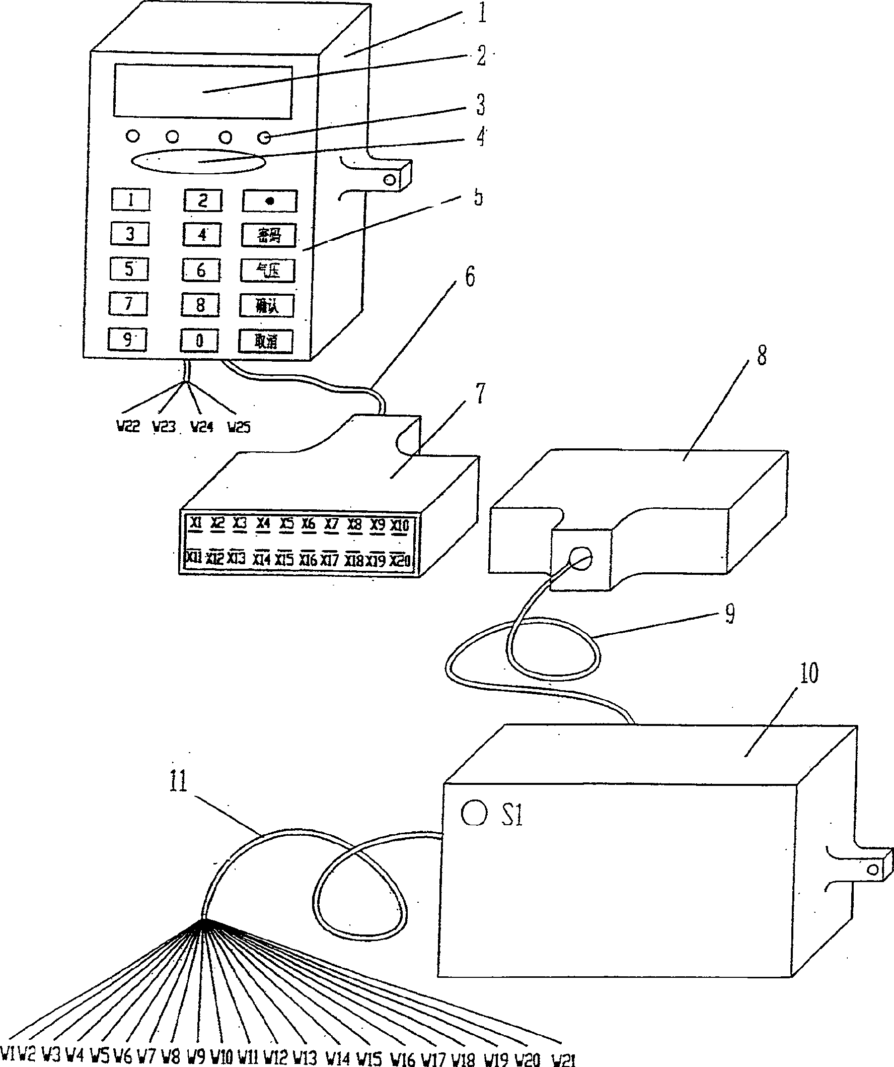
[0066] figure 2 The middle monitor box 1 is connected with the socket 7 through the socket connection cable 6; the plug 8 is connected with the electronic and electrical component box 10 through the plug cable 9; the electronic and electrical component box 10 is connected with the electrical appliance through the connecting electrical cable 11; the monitor box 1 Install liquid crystal display module IC2 (including display screen 2), tire temperature alarm lamp 3 (H1-H4), buzzer 4 (SP), keyboard 5, resistance R1-R3; electronic and electrical component box 11 is equipped with a single-chip microcomputer IC1, DC converter DC-DC, solid state relay SSR1-SSR12, electromagnetic relay K1-K3, chip IC3-IC5, diode V1, V6-V10, crystal oscillator G, resistor R4-R5, capacitor C1-C3;
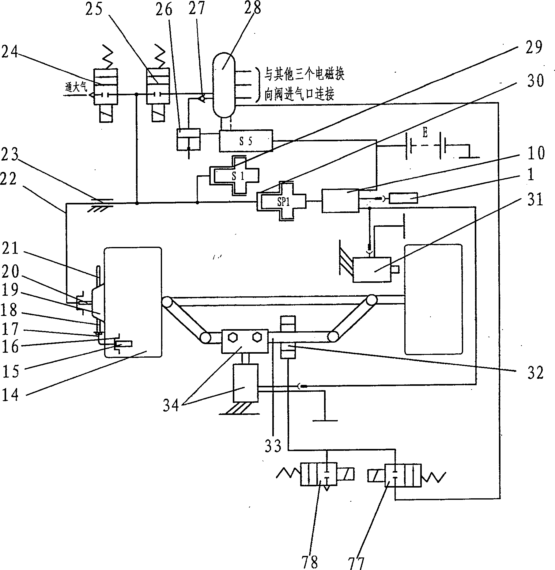
[0067] figure 2Middle: X1-X7 of the socket 7 and plug 8 are the socket plugs ...
PUM
Abstract
The invention discloses a system for real-time monitoring of automobile tire pressure, real-time monitoring of tire temperature, and anti-deflection system for automobile direction due to sudden tire explosion. Cables, plugs and sockets, electronic and electrical component boxes, single-chip microcomputers, chips, crystal oscillators, capacitors, resistors, diodes, DC converters, relays, normally closed switches, tire temperature control circuit switches, tire pressure sensors, tire cutters, anti- Bias clamp, follow-up anti-deflection device, steel pipe, air chamber, iron clip, solenoid valve, air compressor, one-way valve, air storage tank, air control circuit switch, temperature control circuit switch connector, tire pressure sensor connector and car battery and Automobile tires are installed at specified positions and connected with each other in corresponding order. The invention is safe and reliable, simple in structure, easy to manufacture and process, low in cost and good in effect, and can be widely used in various automobiles.
Description
technical field [0001] The invention relates to an intelligent system and working method for monitoring the gas working parameters of automobile tires and related to tires, more specifically, it relates to an automatic real-time monitoring of automobile tire pressure, automatic real-time monitoring of automobile tire temperature, An intelligent system and working method that can prevent the vehicle from veering in the direction of sudden tire explosion. Background technique [0002] At present, there are tire pressure alarm devices on high-end luxury sports cars produced by Mercedes-Benz, BMW, Mitsubishi and other automobile companies, and there are also records of patented technology of automobile tire pressure and temperature alarm devices in the Chinese patent database. The central tire inflation and deflation system (such as the Hummer HUMMER series off-road vehicles produced by General Motors of the United States) is adopted on foreign military and civilian off-road veh...
Claims
Application Information
Patent Timeline
Application Date:The date an application was filed.
Publication Date:The date a patent or application was officially published.
First Publication Date:The earliest publication date of a patent with the same application number.
Issue Date:Publication date of the patent grant document.
PCT Entry Date:The Entry date of PCT National Phase.
Estimated Expiry Date:The statutory expiry date of a patent right according to the Patent Law, and it is the longest term of protection that the patent right can achieve without the termination of the patent right due to other reasons(Term extension factor has been taken into account ).
Invalid Date:Actual expiry date is based on effective date or publication date of legal transaction data of invalid patent.