
Viscometer

A technology of viscosity and viscometer, which is applied in the direction of instruments, measuring devices, scientific instruments, etc., can solve the problems of bending shape of flow tube, impracticability for users, and inability to fully reduce the error of viscosity measurement value, etc.

Inactive Publication Date: 2009-05-27
ENDRESS HAUSER FLOWTEC AG
View PDF18 Cites 0 Cited by
  • Summary
  • Abstract
  • Description
  • Claims
  • Application Information

AI Technical Summary

Problems solved by technology

On the one hand, the pipe the sensor is inserted into must fit the sensor, not the sensor fits the pipe, which may not be feasible for the user
On the other hand, the flow tube may also have a curved shape, so that modifying the position of the installation will not solve this problem
Even with vertically mounted straight flow tubes, the above errors in viscosity measurements cannot be sufficiently reduced
Changes in viscosity measurements of flowing fluids cannot be prevented in this way either

Method used


Image

  • Viscometer
  • Viscometer
  • Viscometer

Examples


Embodiment Construction

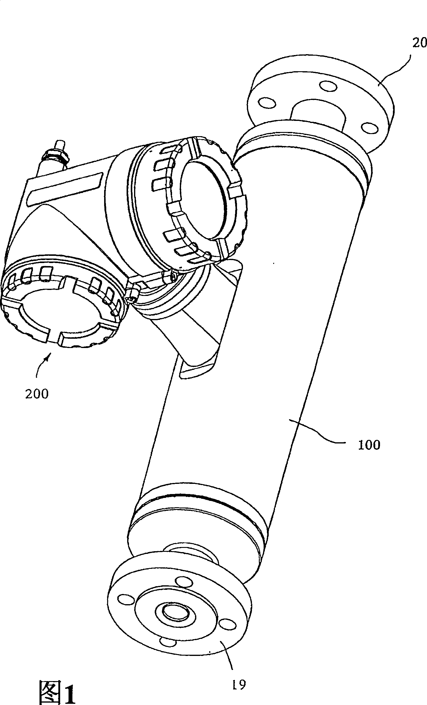
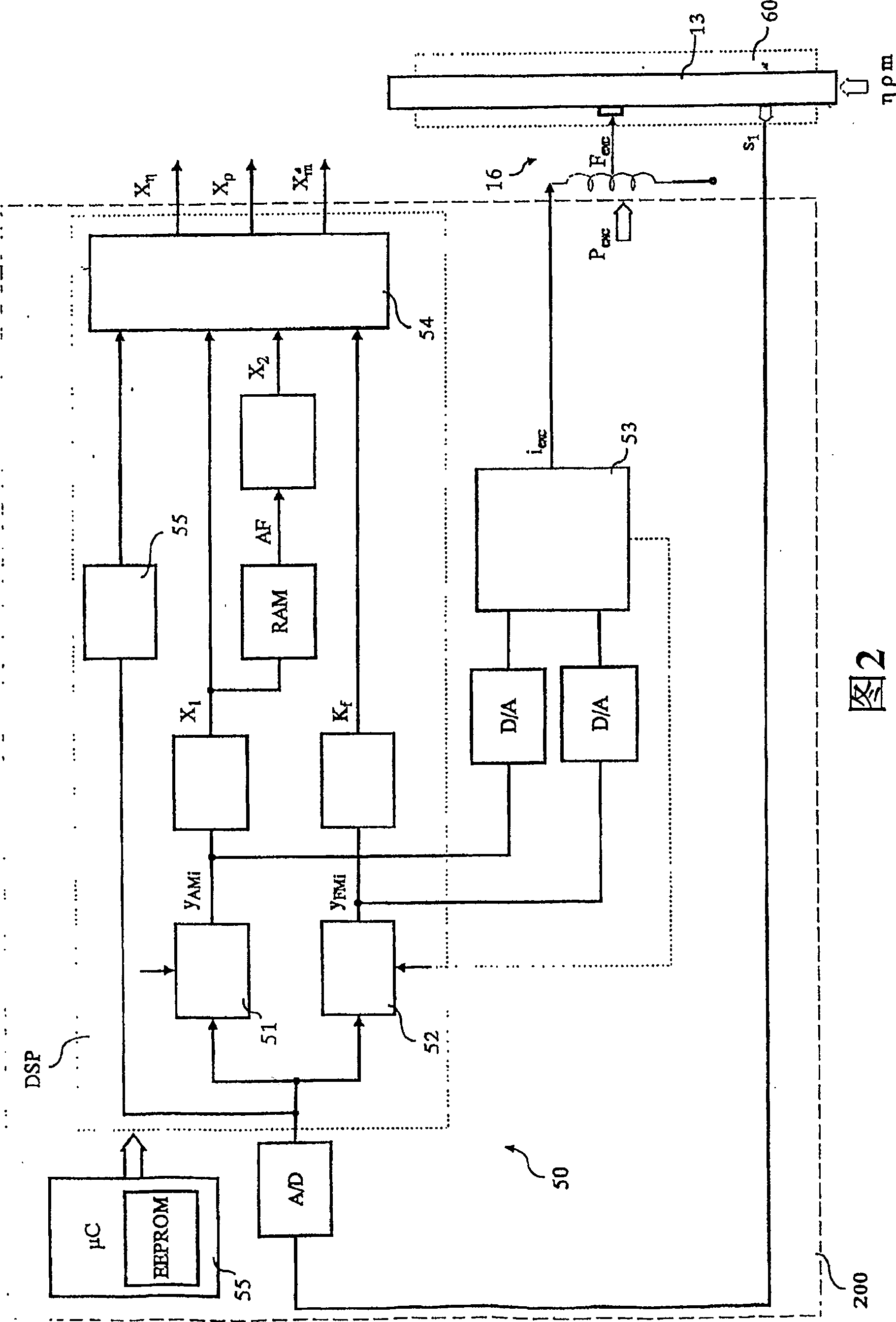
[0068] FIG. 1 schematically shows a viscometer having a vibration sensor 10 preferably housed in a sensor box 100 and electronic measuring equipment 50 housed in an electronics box 200, and as shown in FIG. Shown, and the sensor 10 is electrically connected. The viscometer is used in particular to sense the viscosity η of a fluid flowing in a pipe (not shown) and to map this viscosity to a viscosity measurement X representing this viscosity η η . With the sensor 10 driven by the electronic measuring device 50, a frictional force is generated in the fluid therein, which is related to the viscosity η and acts on the sensor 10 in a measurable manner, i.e. this frictional force can be detected and converted using sensor technology Useful input signal for subsequent electronic evaluation equipment.

[0069] In the preferred case where the viscometer is designed to be connected to a fieldbus, it is preferred that the programmable electronics measuring device 50 include a suitable ...


PUM


Abstract

A viscometer provides a viscosity value (X η ). It comprises a vibration sensor (10) having at least one flow tube (13) connected to the pipeline for guiding the fluid. Driven by the excitation member (16), the flow tube (13) vibrates, causing frictional forces to be generated in the fluid. The viscometer also includes electronic measuring equipment (50), which makes the excitation current (i exc ) flows into the excitation part (16). By means of electronic measuring equipment (50), a first internal intermediate value (X 1 ), which corresponds to the excitation current (i exc ) and thus represent the friction force acting in the fluid. According to the invention, a second internal intermediate value (X 2 ), then the electronic measuring device (50) uses two intermediate values ​​(X 1 , X 2 ) to determine the viscosity value (X η ). First inner median (X 1 ) is preferably utilized to drive the current (i exc ) amplitude control signal (y AM ) normalized, the amplitude control signal corresponds to the vibration of the flow tube (13). As a result, the viscosity value provided by the viscometer (X η ) is highly accurate and robust, especially independent of the installation position of the flow tube (13).

Description

technical field [0001] The present invention relates to a viscometer for a fluid flowing in a pipeline and a method of determining the viscosity of a fluid. Background technique [0002] In detection and automation technology, the viscosity of fluids flowing in pipelines, especially liquids, is usually determined using an instrument that uses a vibration sensor and an electronic measuring device connected to it to sense the internal friction in the fluid and obtain A measurement signal representing the corresponding viscosity is produced. [0003] Such a viscometer is described, for example, in US Patent 4,524,610 or WO-A 95 / 16897, comprising: [0004] - Vibration sensor [0005] -- having a substantially straight flow tube for conducting fluid, said flow tube being connected to the pipeline and vibrating in operation, [0006] --has an excitation part for vibrating flow tubes, [0007] --- the central axis of the vibrating flow tube substantially retains its shape and s...

Claims


Application Information

Patent Timeline
Patent Type & Authority Patents(China)
IPC IPC(8): G01N11/16G01N11/14G01N1/00
CPCG01F1/8418G01F1/8422G01F1/8431G01N11/167G01F1/849G01F1/8413
Inventor 沃尔夫冈·德拉姆阿尔弗雷德·里德
Owner ENDRESS HAUSER FLOWTEC AG
Learn More