
Method for sending signal by specific-dispatching communication terminal

A technology for sending signals and communication terminals, applied in the field of electronic communication, can solve the problems of imperfect circuit function realization, low system reliability, and unstable operation, and achieve the effects of improving energy utilization, high-definition sound quality, and easy operation.

Active Publication Date: 2009-05-06
BEIJING NERA STENTOFON COMM EQUIP CO LTD
View PDF3 Cites 0 Cited by
  • Summary
  • Abstract
  • Description
  • Claims
  • Application Information

AI Technical Summary

Problems solved by technology

Although it can complete the basic work of dispatching, its design idea is backward, the circuit function is not perfect, the cost is relatively high, and the operation is not stable enough. The change of the grid voltage has a great impact on the terminal, which may cause crashes, burnt circuits, etc. situation, the system reliability is low

Method used


Image

  • Method for sending signal by specific-dispatching communication terminal
  • Method for sending signal by specific-dispatching communication terminal
  • Method for sending signal by specific-dispatching communication terminal

Examples


Embodiment Construction

[0035] The specific implementation manner of the present invention will be described below in conjunction with the accompanying drawings.

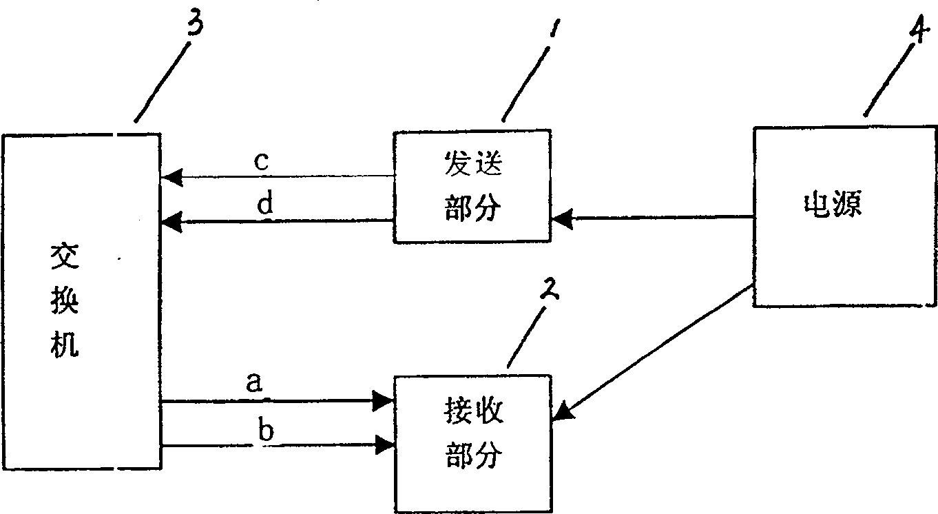
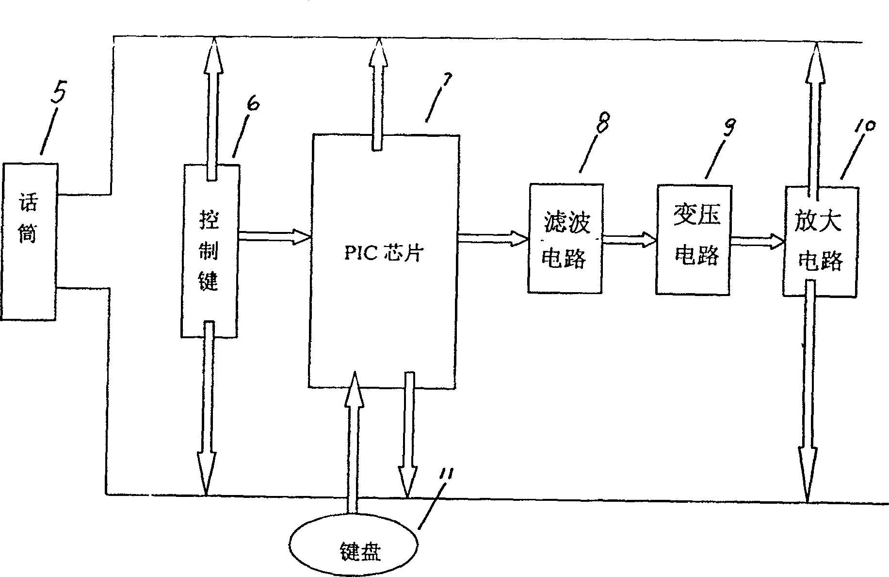
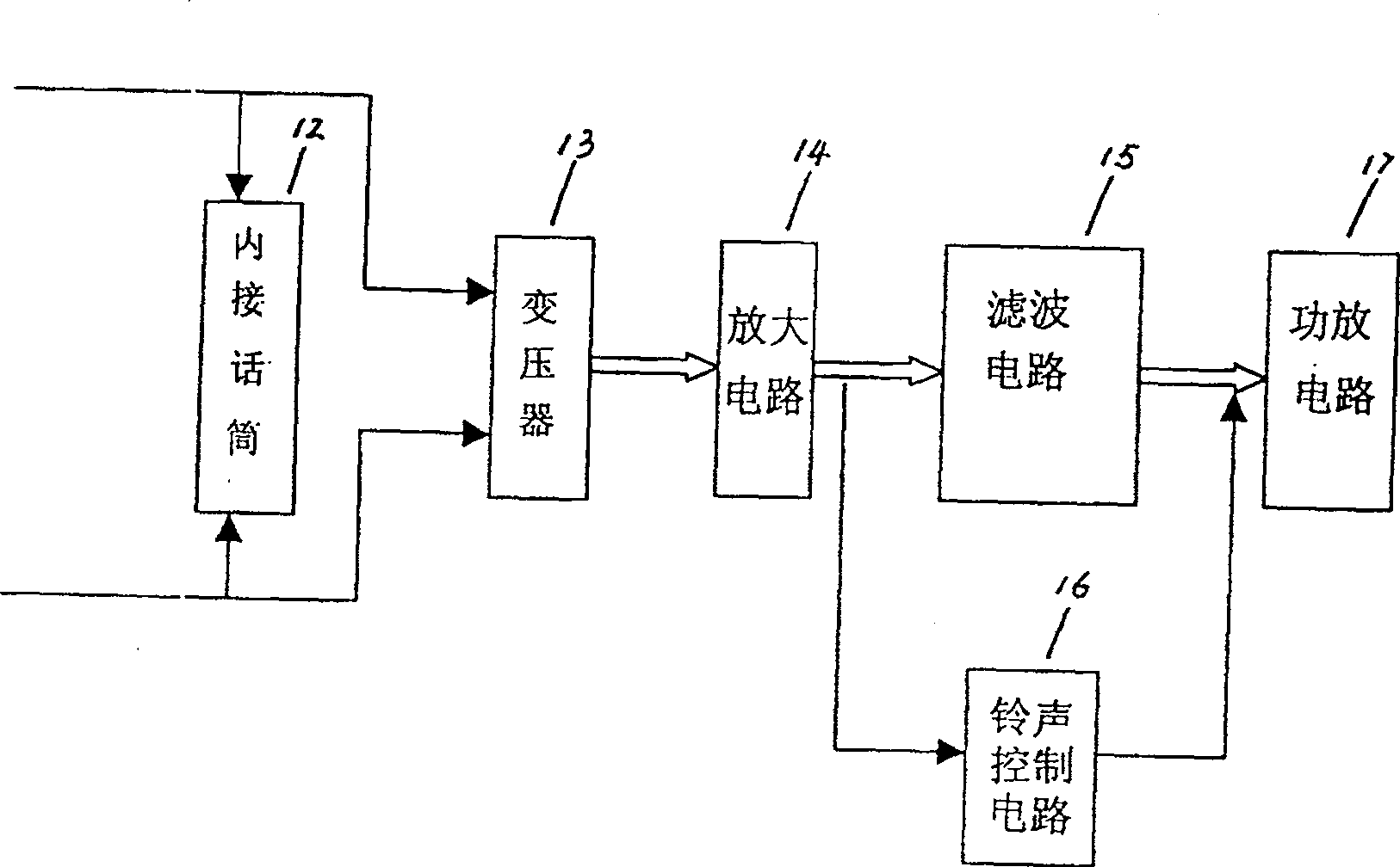
[0036] Such as figure 1 , figure 2 , image 3 As shown, the receiving part 2 is composed of an internal microphone 12, a transformer 13, an amplifier circuit 14, a filter circuit 15, a power amplifier circuit 17, and a ring tone control circuit 16. This part mainly transmits the signal to the terminal through the switch 3 through the ab line, which can be It is converted into an audio signal through a built-in microphone 12; the sending part 1 is composed of a microphone 5, a control key 6, a keyboard 11, a PIC chip 7, a filter circuit 8, a transformer circuit 9, and an amplifier circuit 10, and this part is mainly composed of a control key 6 and a single-chip microcomputer The cd line sends a signal to make the switch 3 know the user's request; the power supply 4 mainly provides the necessary voltage to some basic chips, so that the ch...


PUM


Abstract

The invention discloses a specific dispatching communicating terminal and signal transmitting method, which comprises the following parts: receiving part, sending part, power mode between switchboard and specific dispatching communicating terminal, wherein the voltage of switchboard is changed by the power mode of DC, which supplies power for specific dispatching communicating terminal. The signal transmitting method comprises the following steps: a. affirming main program; b. interrupting sub-program; c scanning keyboard and sub-program of keyboard service; d. sending the sub-program.

Description

technical field [0001] The invention relates to the field of electronic communication, in particular to a dedicated dispatching communication terminal. The invention also relates to a method for sending signals by a dedicated dispatching communication terminal. Background technique [0002] The existing dispatching communication terminal and its method for sending signals include receiving and sending parts, and realize the function of commanding and dispatching through a switchboard. Although it can complete the basic work of dispatching, its design idea is backward, the circuit function is not perfect, the cost is relatively high, and the operation is not stable enough. The change of the grid voltage has a great impact on the terminal, which may cause crashes, burnt circuits, etc. situation, the system reliability is low. Contents of the invention [0003] The technical problem to be solved by the present invention is to avoid the above-mentioned deficiencies in the pr...

Claims


Application Information

Patent Timeline
Patent Type & Authority Patents(China)
IPC IPC(8): H04B1/38G06F9/46H04B1/3883
Inventor 刘及鹤
Owner BEIJING NERA STENTOFON COMM EQUIP CO LTD
Learn More