


Quick Research
Generate reliable direction feasibility study reports for your R&D in just a few steps.

Technical Q&A
Discover and master advanced knowledge NOW. Basics, ideas, possibilities, all at once.

Find Solutions
As an expert in R&D theories, this can generate solutions to your technical problems instantly.

Evaluate Feasibility
Analyze your overall solution with one click, know your potential R&D risks in advance.

Monitor Landscape
Get weekly tech updates, stay abreast of the latest tech innovations and key insights.
Cursor controller and controll method, and its portable electronic device
A cursor control and electronic device technology, applied in the direction of electrical digital data processing, data processing input/output process, instruments, etc., can solve problems such as user inconvenience and limitations, mouse function failure, usage limitations, etc., and achieve precise displacement Detect, reduce the burden, reduce the size of the effect
- Summary
- Abstract
- Description
- Claims
- Application Information
AI Technical Summary
Problems solved by technology
Method used
Image

Examples
no. 1 example
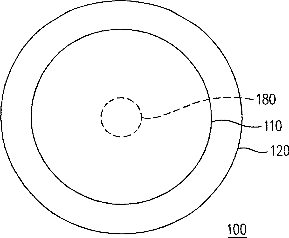
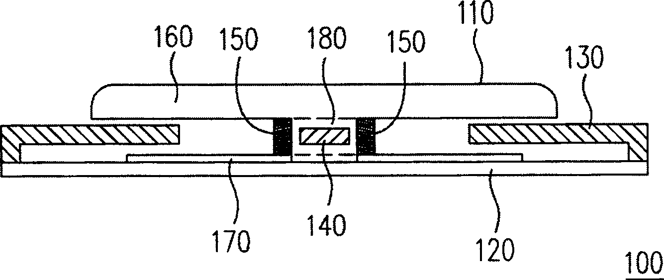
[0035] figure 1 and figure 2 They are a top view and a cross-sectional view of the cursor control device according to the first embodiment of the present invention, respectively. Please also refer to figure 1 and figure 2 , the same label in the figure represents the same object. The cursor control device 100 of this embodiment is used to control the cursor on the display screen, which mainly includes an optical mouse 110 , a pad 120 and a protective device 130 , and the optical mouse 110 is provided with a light sensor 140 and a plurality of pressure sensors 150 . The detailed functions of each object are described below:
[0036] like figure 2 As shown, the optical mouse 110 of this embodiment includes an upper disc 160 and a lower disc 170 , and the two are connected by a support 180 . In addition, the optical sensor 140 is arranged in the pillar 180 , and a plurality of pressure sensors 150 are arranged around the pillar 180 . Wherein, the light sensor 140 is ju...
no. 2 example
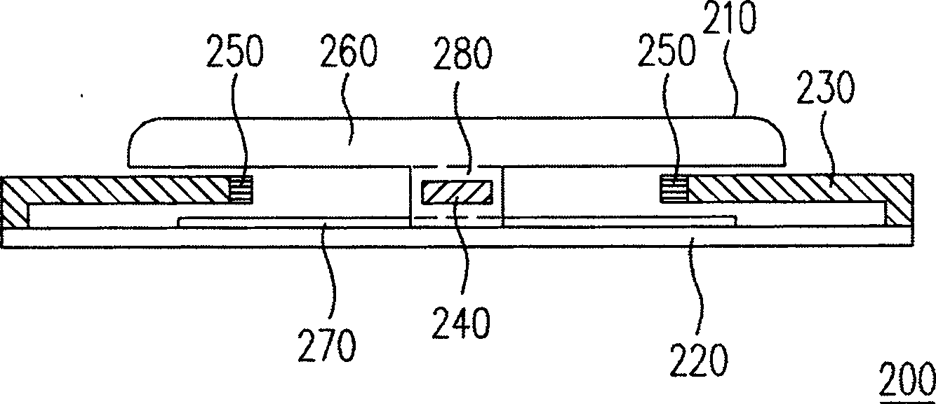
[0044] image 3 It is a cross-sectional view of a cursor control device according to a second embodiment of the present invention. Please refer to image 3 , the cursor control device 200 of this embodiment is used to control the cursor on the display screen, which mainly includes an optical mouse 210, a pad 220 and a protective device 230, and the optical mouse 210 is configured with a light sensor 240 and a plurality of pressure sensors 250. Different from the first embodiment, the pressure sensor 250 of this embodiment is disposed around the hole in the protective device 230 , and the configurations and functions of other objects are the same as those of the first embodiment, so they are not repeated here.
[0045] In this embodiment, when the optical mouse 210 moves to the edge of the fixed plane, the pillar 280 of the optical mouse 210 will touch the pressure sensor 250 around the hole in the protective device 230 , and the cursor control device 200 will respond accordi...
no. 3 example
[0052] Based on the cursor control devices described in the first and second embodiments above, a special cursor control method can be derived, that is, combining the characteristics of the optical sensor and the pressure sensor, and matching the moving position of the optical mouse, the displacement direction and Displacement and other movement information, and then achieve the purpose of controlling the cursor movement.
[0053] Image 6 It is a flowchart of a cursor control method drawn according to the third embodiment of the present invention. Please refer to Image 6 , the present embodiment is to control the cursor on the display screen by detecting the displacement information of the optical mouse moving on a pad, and the displacement information generated according to the position of the contacted pressure sensor. The steps are described in detail as follows:
[0054]First, a frame reflected on the pad is captured by the optical sensor on the optical mouse as a refe...
PUM
 Abstract
Description
Claims
Application Information
 - R&D Engineer
- R&D Manager
- IP Professional
- Industry Leading Data Capabilities
- Powerful AI technology
- Patent DNA Extraction
Browse by: Latest US Patents, China's latest patents, Technical Efficacy Thesaurus, Application Domain, Technology Topic, Popular Technical Reports.
© 2024 PatSnap. All rights reserved.Legal|Privacy policy|Modern Slavery Act Transparency Statement|Sitemap|About US| Contact US: help@patsnap.com