
Self-adapting wire coil to power of induction cooker

A self-adaptive, induction cooker technology, applied in applications, household stoves/stoves, electric heating fuels, etc., can solve problems such as bursting, wire coil insulation breakdown, adverse resonance, etc., to alleviate the influence of thermostat and automatic functions, and improve power factor, optimizing the effect of electromagnetic coupling

Active Publication Date: 2009-05-06
HONGYANG HOME APPLIANCES
View PDF5 Cites 0 Cited by
  • Summary
  • Abstract
  • Description
  • Claims
  • Application Information

AI Technical Summary

Problems solved by technology

The strength of the magnetic field line in this part has small energy when the current is small, and the energy is also large when the current is high. It is just not conducive to resonance when the power is low, and it is easy to generate high back pressure when the power is high, which may cause IGBT burnout and coil insulation. Breakdown and other faults; at the same time, if the pot is suddenly removed during the use of the induction cooker, the upper part with the ring-shaped magnetizer is also prone to the danger of bursting

Method used


Image

  • Self-adapting wire coil to power of induction cooker
  • Self-adapting wire coil to power of induction cooker
  • Self-adapting wire coil to power of induction cooker

Examples


Embodiment Construction

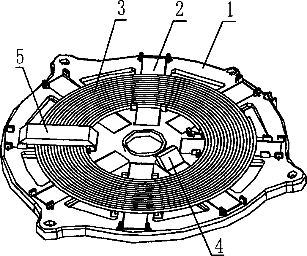
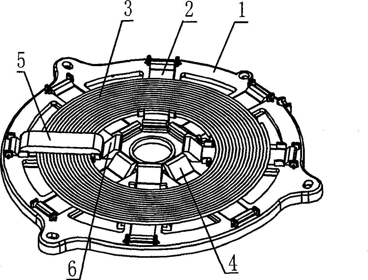
[0020] like figure 1 As shown, a power self-adaptive wire reel for an induction cooker includes a bracket 1, a radially distributed magnetic strip 2, and a coil 3 fixed on the bracket. The proximal end of the magnetic strip has an upward corner 4, and the height of the corner 4 is greater than the height of the upper surface of the annular magnetizer, with a height difference of 3mm.

[0021] Of course, the annular magnetizer is formed by enclosing one of the magnetic strips and the magnetizer.

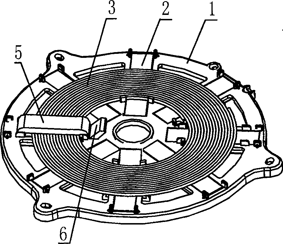
[0022] like figure 2 As shown, an induction cooker power self-adaptive reel includes a bracket 1, a radially distributed magnetic strip 2, a fixed coil 3 on the bracket, and the coils 3 all pass through a ring-shaped magnetizer 5, and the ring-shaped magnetizer 5 The proximal end has an upward corner 6, and the height of the corner 6 is greater than the height of the upper surface of the annular magnetizer, with a difference of 0.1mm in height.

[0023] like image 3 As shown, an...


PUM


Abstract

This invention relates to a power adaptive wire coil of induction cookers including a bracket, magnetic strips distributed in radiation and a coil fixed on the bracket characterizing that part or whole of the coil passes through at least one ring magnetizer and the near-core end of at least one magnetic strip includes an upward corner higher than the top surface of the ring magnetizer to avoid burning down the upper part of the magnetizer with extra numbers of magnetic lines passing through at sudden unload.

Description

technical field [0001] The invention relates to a wire reel for an electromagnetic oven. Background technique [0002] The induction cooker uses the principle of electromagnetic induction to generate eddy current to heat the pot. During the working process, there is a gap between the magnetic strip of the reel and the pot. In this gap, there will be magnetic force lines passing through, and some of them will not pass through the pot. , can be regarded as magnetic flux leakage to a certain extent. The strength of the magnetic field line in this part has small energy when the current is small, and the energy is also large when the current is high. It is just not conducive to resonance when the power is low, and it is easy to generate high back pressure when the power is high, which may cause IGBT burnout and coil insulation. Breakdown and other faults; at the same time, when the pot is suddenly removed during the use of the induction cooker, the upper part with the ring-shape...

Claims


Application Information

Patent Timeline
Patent Type & Authority Patents(China)
IPC IPC(8): F24C7/08
Inventor 朱泽春王宁金延东
Owner HONGYANG HOME APPLIANCES
Learn More