
Inertia separator

A technology of inertial separator and separator, which is applied in the field of coal grinding and can solve problems such as existence

Active Publication Date: 2009-04-15
泰亚兹马斯股份公司
View PDF4 Cites 0 Cited by
  • Summary
  • Abstract
  • Description
  • Claims
  • Application Information

AI Technical Summary

Problems solved by technology

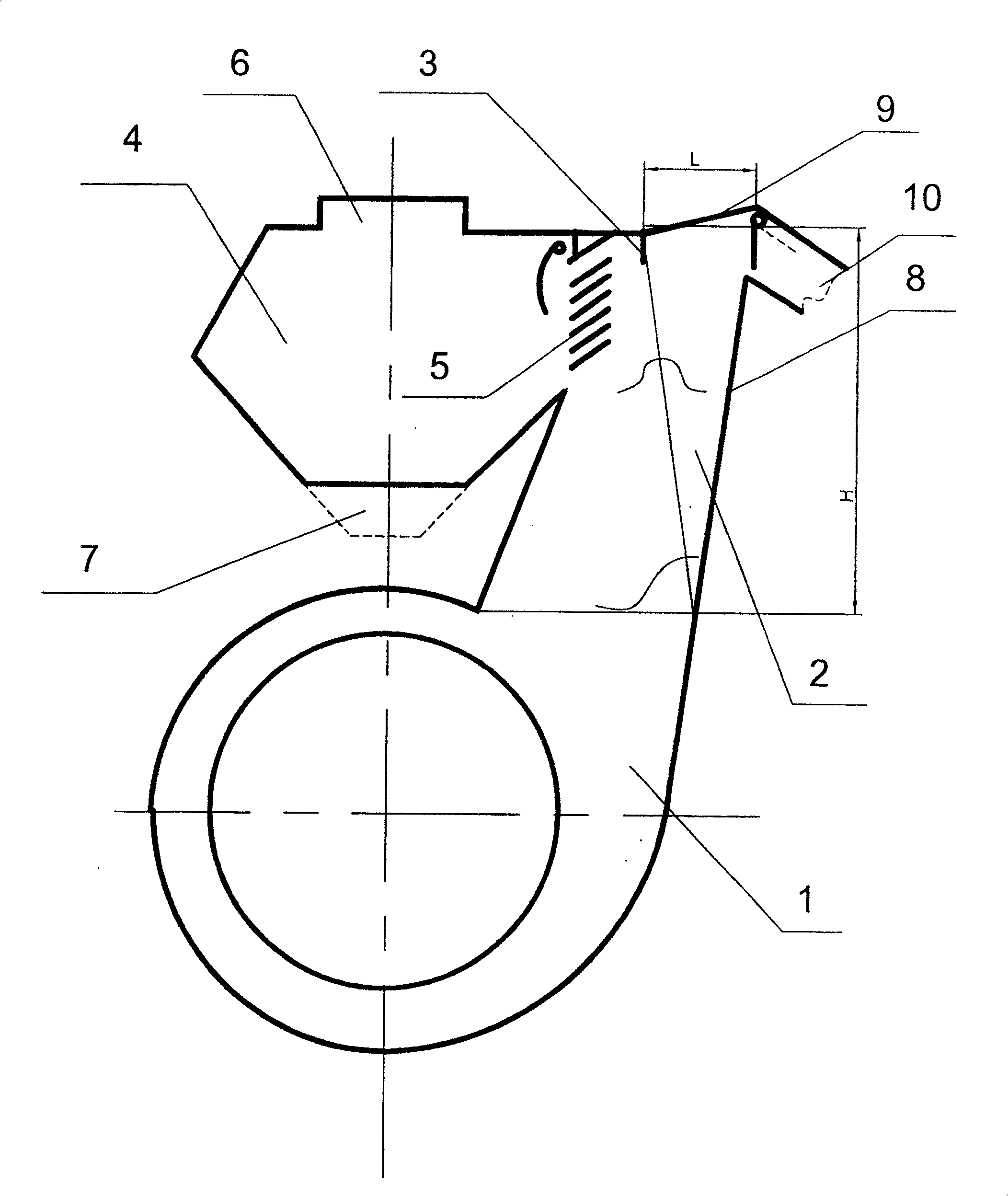
[0006] A disadvantage of this known inertial separator is also the presence of coarse-grained components in the finished dust, since there is no obstruction on the path of the coarse-grained components to the upper nozzle of the slat-plate nozzle grille

Method used


Image

  • Inertia separator

Examples


Embodiment Construction

[0013] The inertial separator comprises a grinding chamber 1 , a feed channel 2 connected thereto, and a partition 3 connected to the upper part of the feed channel 2 . The partition plate 3 separates the separation chamber 4 with the fish-scale plate type nozzle grid 5, the product dust outlet pipe 6 and the return leak nozzle 7 from the supply channel 2. The partition plate 3 is installed on the upper part of the supply channel 2, and is set to a distance L to the outer wall 8 of the supply channel 2, satisfying L≥(0.25-0.3)H, where H-the height of the supply channel 2. The upper wall 9 of the supply channel 2 is installed obliquely, gradually rising towards the side of the outer wall 8 of the supply channel 2 . The upper part of the supply channel 2 is provided with an outlet pipe 10 for coarse grain components, which is inclined downward.

[0014] Inertial separators work in the following ways:

[0015] The ground product from the grinding chamber 1 is conveyed to the fe...


PUM


Abstract

The invention relates to a milling machine in the energy industry. The invention can be used in building, chemistry and other industry. A separator is set on the upper wall of the supply passage of an inertia separator. The inertia separator has a passage providing the milling product and an inertia vapor head comprising a shiplap-spout grid and a transfer pipe of the finished goods dust. The separator is set at the distance L which is equal or greater than 0.25-0.3H wherein the H is the height of the passage to the passage's outer wall, and the length of the separator is not less than the height of the upper spout of the shiplap-spout grid. The upper wall of the supply passage is made as incline and hoisted gradually toward the outer wall, the upside of the passage has a decline transfer pipe which is used to clear the coarse component.

Description

technical field [0001] The invention relates to coal grinding technology and can be used in energy, construction, chemical and other industrial industries. Background technique [0002] Known a kind of inertial separator, has separation chamber, has feed inlet, wherein installs fish-scale plate spout grate, and the discharge port of the upper spout of grate is installed the ram that rotates (SU No.579037, BO7B 7 / 00). [0003] A disadvantage of the known inertial separators is the presence of coarse-grained components in the finished dust, which impair the combustion of the fuel and, as a result, the operating economy of the plant. [0004] The above-mentioned disadvantages are due to the fact that the main part of the coarse dust enters the upper nozzle of the fish-scale nozzle grid by inertia force, and then enters the upper part of the separation chamber. A discharge pipe for the finished dust is provided here, and the part of the coarse particles falls into the above d...

Claims


Application Information

Patent Timeline
Patent Type & Authority Patents(China)
IPC IPC(8): B07B7/02B02C23/12B07B4/00B07B7/00
Inventor K·N·斯捷潘诺维奇V·A·鲍里索维奇L·V·西诺维耶维奇A·V·维克托罗维奇T·U·根纳季耶维奇T·V·瓦西里耶维奇
Owner 泰亚兹马斯股份公司
Learn More