
Shiplap plate seal

a technology of seals and plate covers, which is applied in the direction of engine seals, leakage prevention, machines/engines, etc., can solve the problems of rare use of heavy-duty gas turbines and poor seal performan

Inactive Publication Date: 2013-10-03
GENERAL ELECTRIC CO
View PDF7 Cites 0 Cited by
  • Summary
  • Abstract
  • Description
  • Claims
  • Application Information

AI Technical Summary

Benefits of technology

The invention is about a seal plate assembly for a turbine rotor that includes inner and outer seal plates. The seal plates and shiplaps are designed so that when the shiplaps are in contact, there is a gap between the outer seal plate and the rotor or between the inner seal plate and the rotor or bucket hook. This design helps to improve the sealing efficiency of the turbine rotor and reduce the leakage of gas.

Problems solved by technology

Full hoop coverplates provide effective seals, but can rarely be used in heavy duty gas turbines due to field maintenance requirements and the difficulty of unstacking the unit rotor in the field.
Segmented seals have the problem that in some cases the seal performance is not satisfactory.

Method used


Image

  • Shiplap plate seal
  • Shiplap plate seal
  • Shiplap plate seal

Examples


Embodiment Construction

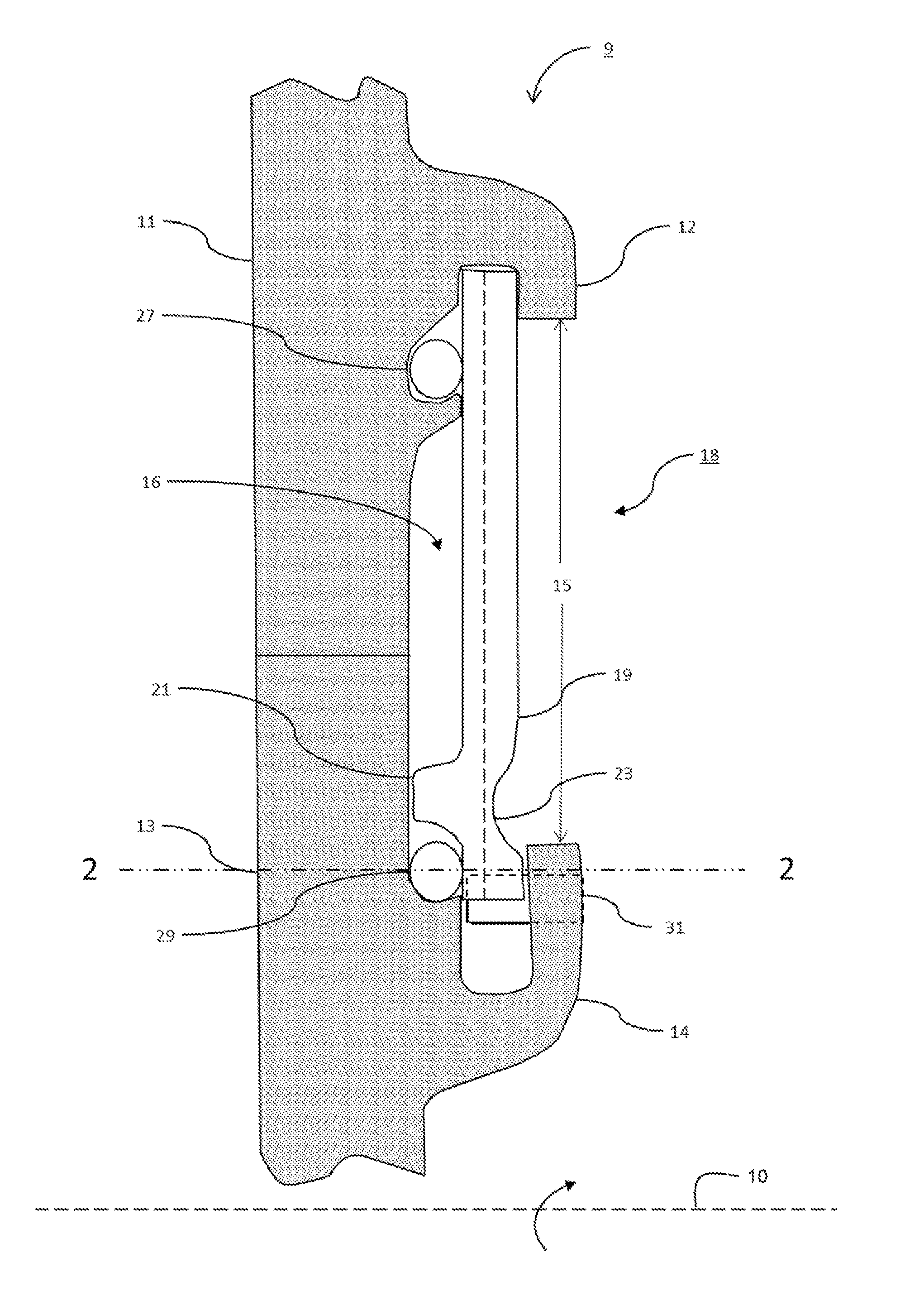
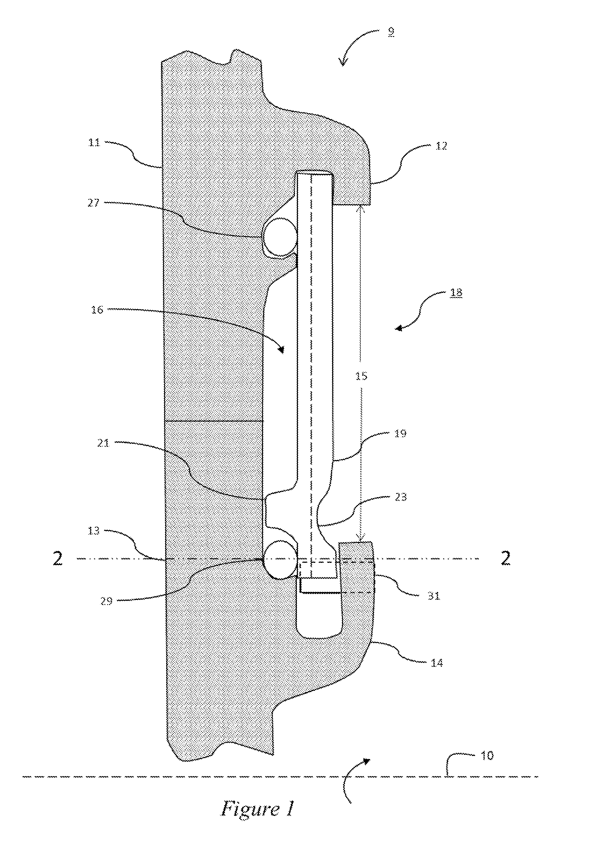
[0010]Illustrated in FIG. 1 is an embodiment of a rotor assembly 9 that may be used in a turbine system. The rotor assembly 9 rotates about an axis 10, and may include at least one turbine blade 11 having a blade flange 12. The blade flange 12 protrudes from the turbine blade 11 and angles towards the axis of rotation of the rotor assembly 9. The turbine blade 11 is secured to a rotor 13 by conventional means, such as for example a dovetail structure. The rotor 13 may be provided with a rotor flange 14 that protrudes from the rotor 13 and angles away from the axis of rotation of the rotor assembly 9. The blade flange 12 and the rotor flange 14 define an opening 15 and a chamber 16.

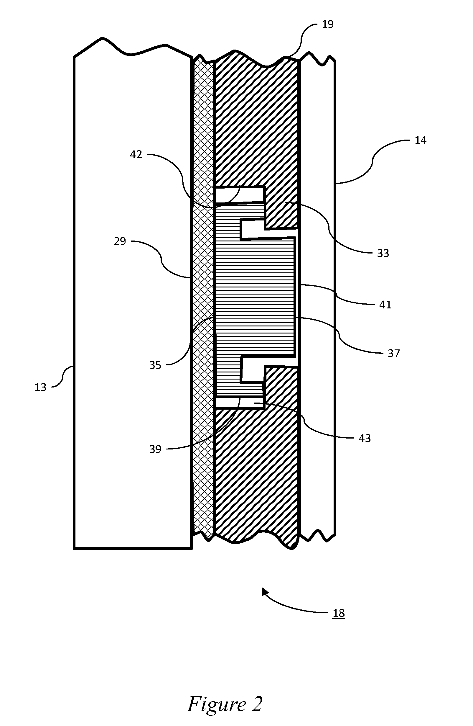
[0011]Disposed in the chamber 16 is a seal assembly 18 that may include an inner shiplap seal plate 19. The at least one inner shiplap plate 19 may include a rim 21 and an indented portion 23. The indented portion 23 provides clearance between the at least one inner shiplap plate 19 and the rotor flange 14...


PUM


Abstract

A seal plate assembly for a turbine rotor includes at least one inner shiplap seal plate disposed on the rotor; and at least one outer seal plate adapted to engage the at least one inner shiplap plate. The thickness of the at least one outer seal plate is different than the thickness of the at least one inner shiplap plate causing either the at least one inner shiplap plate or the at least one outer seal plate to come into contact first under centrifugal load.

Description

TECHNICAL FIELD[0001]The subject matter disclosed herein relates to gas turbine rotors and, more particularly, is concerned with a seal assembly for sealing coolant passageways in turbine rotor blades disposed in the periphery of a turbine rotor disc.BACKGROUND[0002]A typical gas turbine has a rotor (wheel) with a number of blades (buckets) distributed around the circumference of the rotor. The blades may be secured to the rotor using a conventional dovetail configuration. The blades are driven by hot gas from the combustion chamber and are cooled using a coolant that flows through passages in the blades. It is important to avoid the hot gases from coming into contact with the rotor.[0003]A variety of seal configurations have been developed to prevent the hot gases from coming into contact with the rotor. In some cases a full hoop coverplate may be positioned about the rim of rotor to seal off the hot gases. The seal assembly may also seal a cavity between the blades and the rotor d...

Claims


Application Information

Patent Timeline
IPC IPC(8): F16J15/02
CPCF01D11/006F01D5/3015
Inventor HAFNER, MATTHEW TROY
Owner GENERAL ELECTRIC CO
Learn More