
Method for transmitting active reporting information of equipment

A technology of active reporting and equipment, applied in transmission systems, digital transmission systems, electrical components, etc., can solve problems such as lack of end-to-end reliability, and achieve the effect of wide application and timely transmission

Inactive Publication Date: 2009-03-18
ZTE CORP
View PDF4 Cites 0 Cited by
  • Summary
  • Abstract
  • Description
  • Claims
  • Application Information

AI Technical Summary

Problems solved by technology

[0006] The purpose of the present invention is to provide a method for transmitting the information actively reported by the equipment, and propose a new method from the application level to solve the trap, that is, the reliable transmission of the actively reported data, and fundamentally ensure the integrity of the actively reported data at the application level End-to-end reliability, to overcome the lack of end-to-end reliability in the process of actively reporting device information in the prior art

Method used

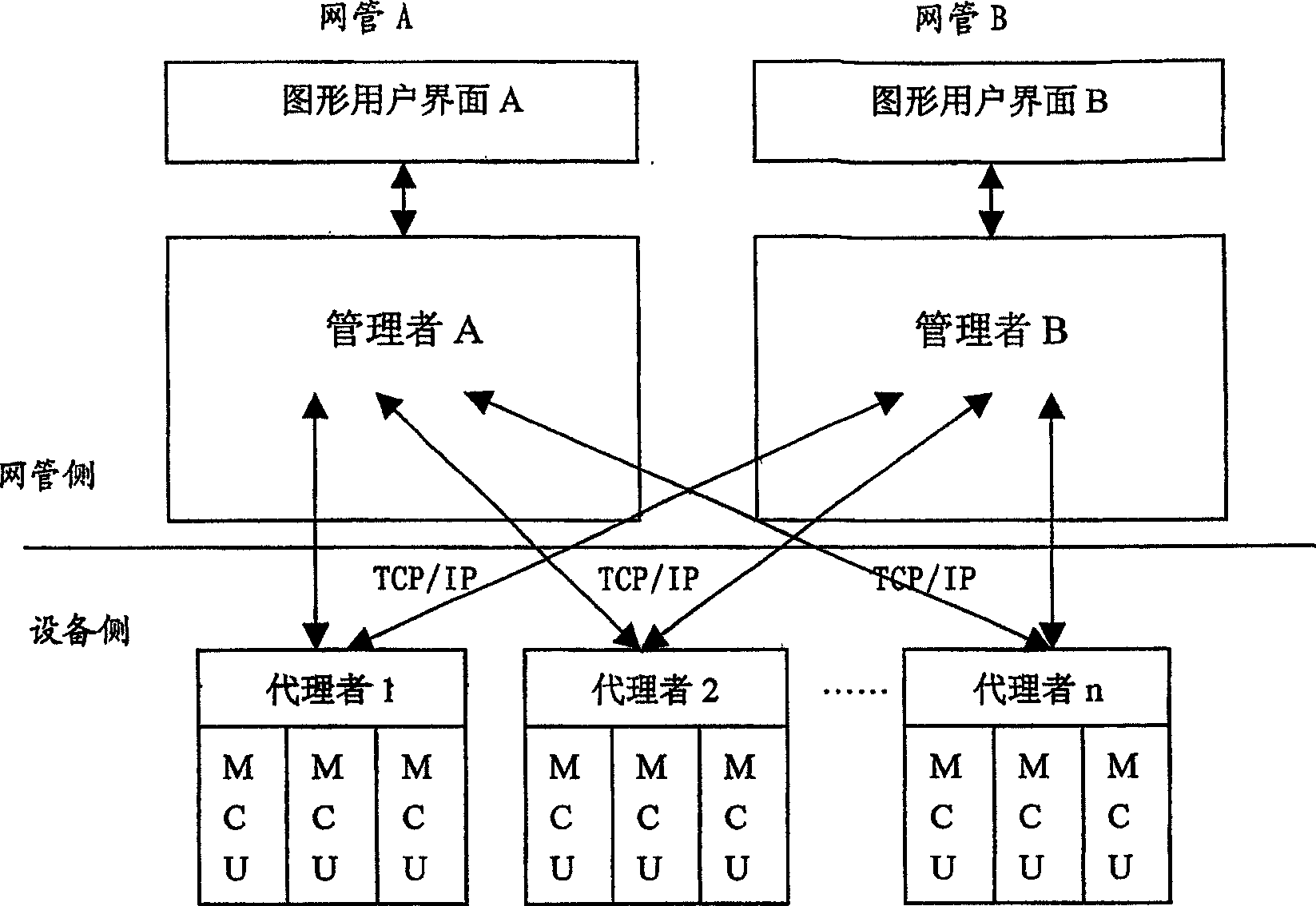
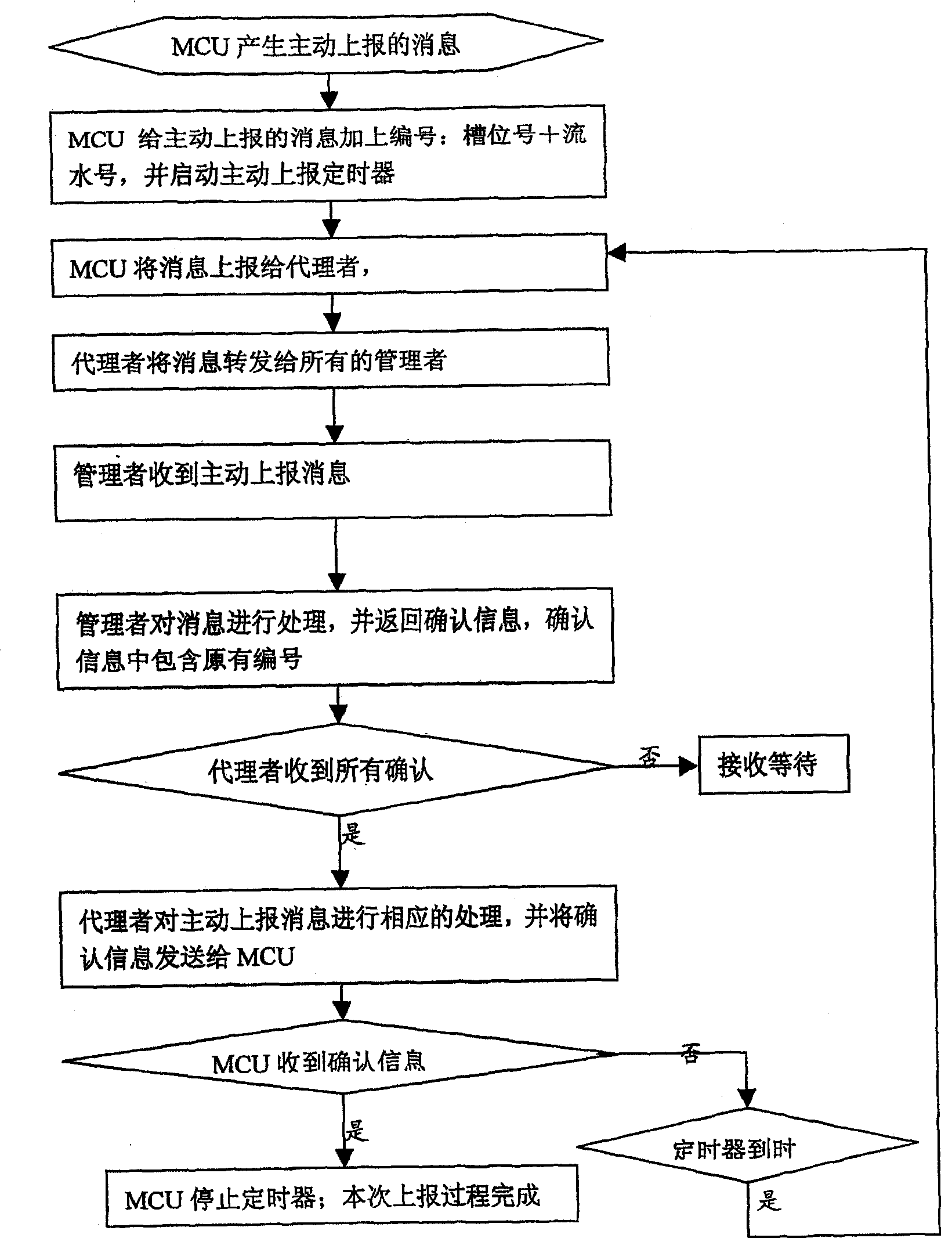
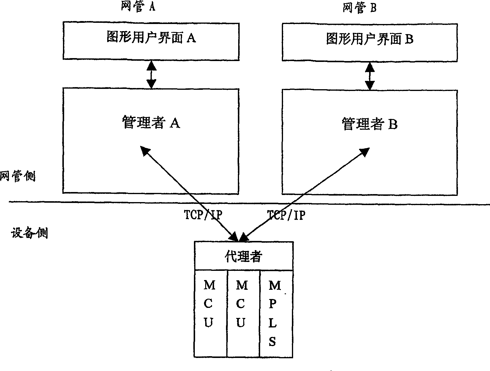

Image

  • Method for transmitting active reporting information of equipment
  • Method for transmitting active reporting information of equipment
  • Method for transmitting active reporting information of equipment

Examples


Embodiment 1

[0042] The composition of the network management system in this example is as follows: image 3 As shown, it includes four parts: graphical user interface, manager, agent, and management control unit (MPLS is the MCU that completes the embedded MPLS function). Manager B. In the case of the entire network, each device in the network can be viewed separately, so the method of the present invention can also be applied.

[0043] The work flow chart of the example of the present invention is as figure 2 shown.

[0044] In this embodiment, the description of the present invention is carried out by taking the embedded MPLS system in the MSTP system as an example. In the MSTP embedded MPLS system, the MPLS single board is used as an MCU (management control unit) to complete the MPLS function in the MSTP system. The process of reliably and actively reporting the LSP configuration data automatically generated by the control plane to the background network management is the problem to ...

Embodiment 2

[0059] The composition of the network management system in this embodiment is as follows Figure 4 As shown, it includes four parts: graphical user interface, manager, agent, and management control unit (ICP is the MCU that completes the ASON control function). b. In the case of the entire network, each device in the network can be treated individually, so the present invention is also applicable.

[0060] The work flow chart of the example of the present invention is as figure 2 shown.

[0061] In this embodiment, the method of the present invention is described by taking the active reporting of time slot data automatically generated by the ICP in the ASON system as an example. In the ASON system, each device can automatically generate time slot configuration data according to the network operating conditions. The process of reliable and active reporting of data to the background network management is the problem to be solved by the present invention.

[0062] Step 1: N...


PUM


Abstract

A method for transferring the information which is reported by the device initiatively, comprises the following steps: the management control unit uniquely identifies the initiatively reporting message, and reports it to the manager through the agent; upon receiving the agent's message, the manager processes the data and gives back an acknowledgement information with number to the agent; the agent transfers the acknowledgement information to the management control unit, then the reporting course is end; unless the management control unit receives the acknowledgement information, it reports the message initiatively, periodically and repeatedly. The method according to the invention ensures that the information reported by the device initiatively is transferred reliably and in time. Consequently, it ensures the data conformity between the network manager and the device under all kinds of operation modes.

Description

technical field [0001] The invention relates to a method for realizing reliable information transmission between equipment and a network manager in the information field, and in particular to a method for actively reporting device information to a background network manager in the information technology field. Background technique [0002] In the field of network management of information technology, the Simple Network Management Protocol (SNMP / RFC2271) is a de facto industrial standard due to its advantages of simplicity, practicality, and architecture development. On the one hand, a large number of network management systems use SNMP to complete Device configuration and monitoring; on the other hand, private network management that does not use the SNMP standard protocol is actually deeply affected by SNMP in terms of operation methods and system structure. Generally speaking, private network management and SNMP network management are the same in terms of system architectu...

Claims


Application Information

Patent Timeline
Patent Type & Authority Patents(China)
IPC IPC(8): H04L12/24H04L29/06
CPCH04L41/046
Inventor 段磊令
Owner ZTE CORP
Learn More